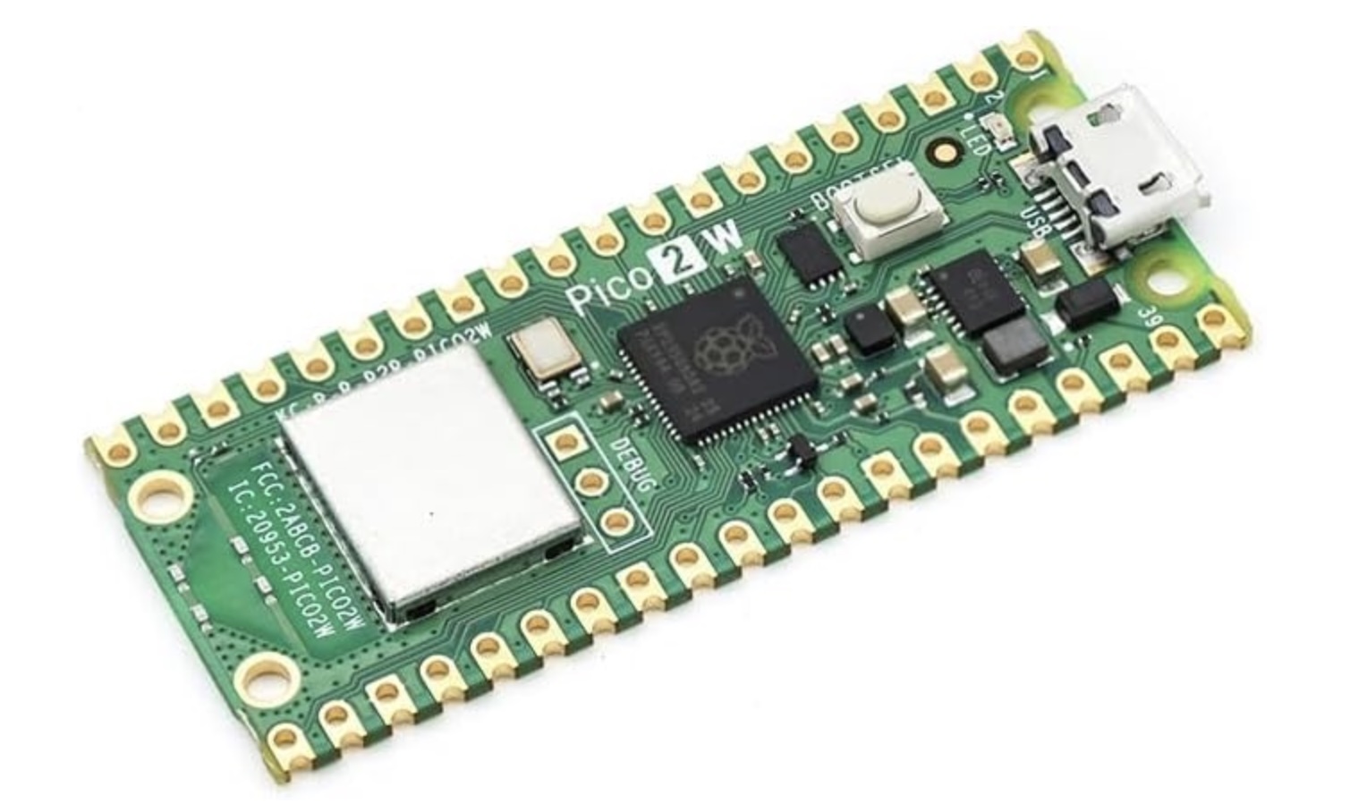
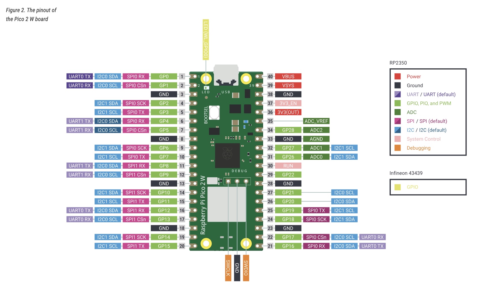
Raspberry Pi Pico 2 W Specifications
| Microcontroller | Raspberry Pi RP2350 (dual-core Arm Cortex-M33 + dual-core RISC-V Hazard3) |
|---|---|
| Clock Speed | Up to 150 MHz |
| SRAM | 520 KB on-chip |
| Flash Memory | 4 MB QSPI flash |
| Wireless |
2.4 GHz Wi-Fi (802.11n) Bluetooth 5.2 |
| GPIO Pins | 26 multi-function GPIO |
| Interfaces |
2 × UART 2 × SPI 2 × I²C USB 1.1 (device) 16 × PWM channels 3 × 12-bit ADC |
| Operating Voltage | 1.8V – 5.5V input (3.3V logic) |
| Dimensions | 51 mm × 21 mm |
| Release Year | 2024 |
Note: ChatGPT was used to assist with code development and Raspberry Pi setup.
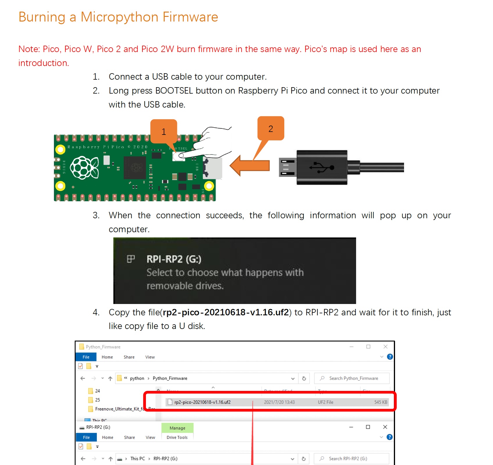
Burning Micropython Firmware
The Raspberry Pi Pico supports both Python (MicroPython) and C/C++ development. Firmware can be flashed to enable either environment. The board includes 4MB of onboard Flash memory for firmware and user programs.
I have more experience in C/C++, but decided to use Python as a learning experience. It’s faster to prototype with and easier to iterate on.
Besides… all the cool kids are using Python!
With the 4MB Flash memory, there is plenty of space for embedded projects:
- MicroPython firmware: ~600–800 KB
- Filesystem available for user code: ~3 MB
- Simple Python file: typically 1–5 KB
- Medium Python project: typically 10–50 KB
- Enough room to store multiple projects and reusable helper libraries
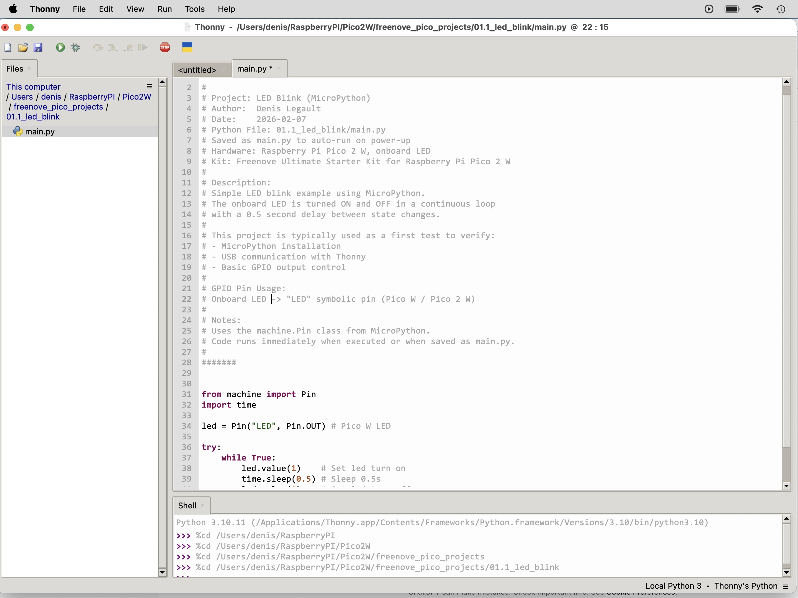
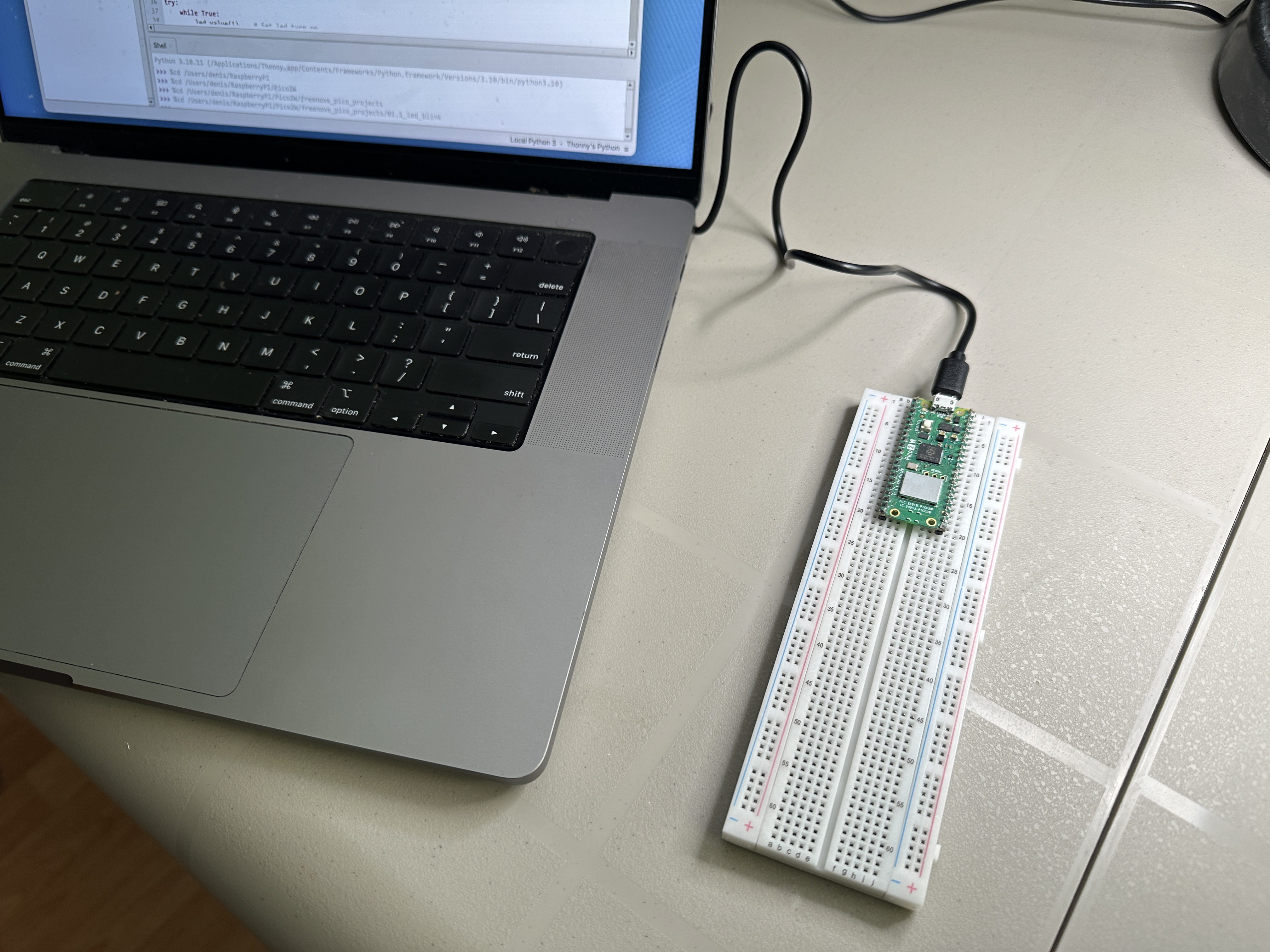
Thonny Python IDE
Thonny is a lightweight Python IDE with built-in support for MicroPython devices such as the Raspberry Pi Pico.
When you click Run, Thonny transfers the script to the Pico over USB and executes it directly in RAM for fast testing and iteration.
If the program is saved as main.py on the Pico’s flash filesystem, it will automatically execute on power-up.
Description
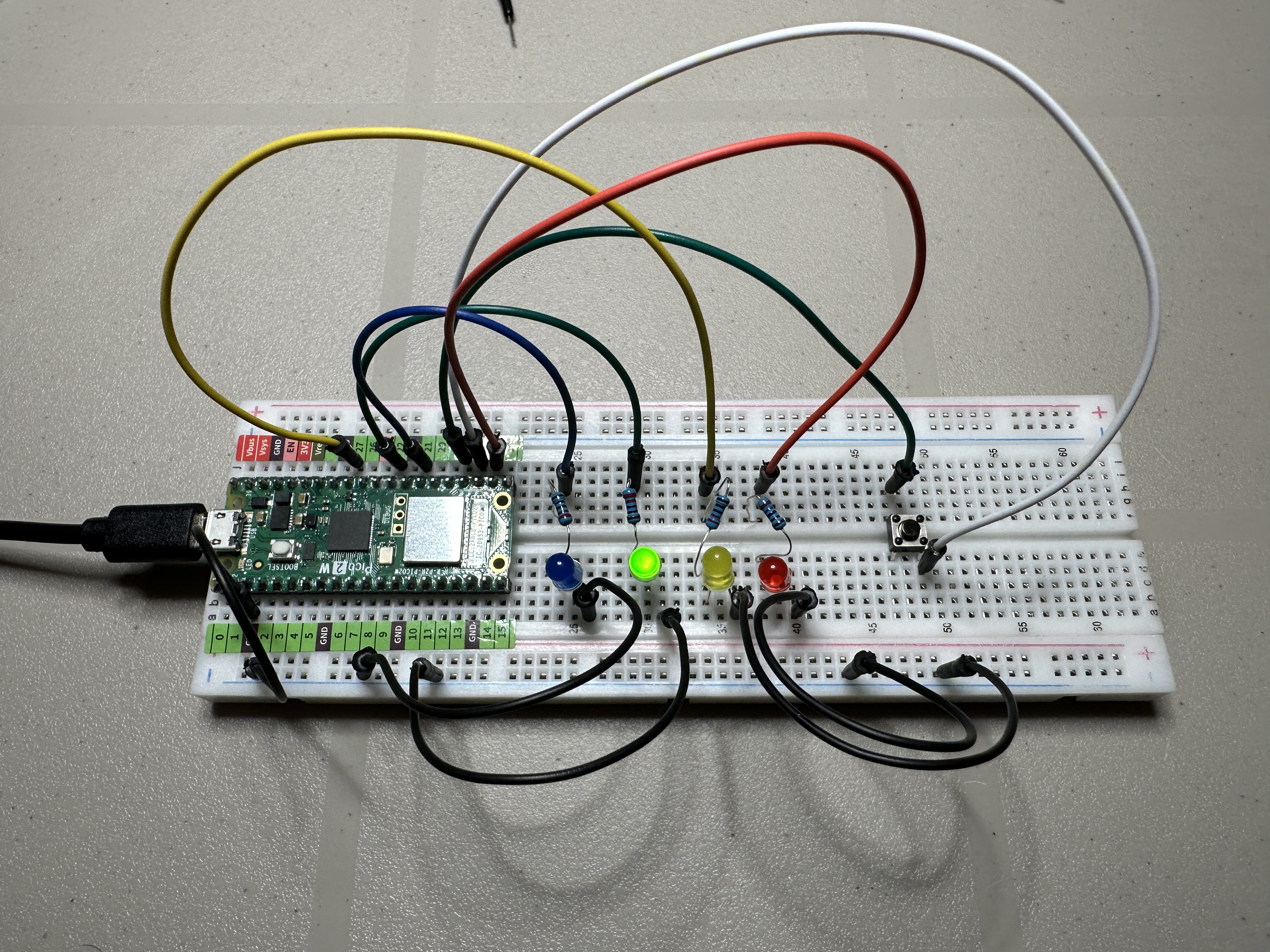
Simulates a traffic light system with a pedestrian crossing using the Raspberry Pi Pico 2 W. The traffic lights normally cycle through Green → Yellow → Red to represent the flow of vehicle traffic.
When the pedestrian push button is pressed, the system waits until the next safe stopping point, then turns the traffic light red and activates a pedestrian “WALK” signal using a blue LED. The walk signal stays solid for several seconds before blinking to warn that the crossing time is ending. Traffic then resumes normal operation.
Features
- Traffic light sequence: Green → Yellow → Red
- Pedestrian push button to request a crossing
- Blue LED used as the pedestrian “WALK” signal
- Walk signal turns solid ON then blinks before ending
- Non-blocking firmware design using millisecond timing
- State-machine architecture for responsive control
- Designed to run automatically when saved as
main.py
Hardware
- Raspberry Pi Pico 2 W
- Red, Yellow, Green LEDs for traffic light
- Blue LED for pedestrian walk signal
- Push button for pedestrian request
Resulting Behavior
| Phase | Car Lights | Pedestrian LED |
|---|---|---|
| Normal | Green | Off |
| Transition | Yellow | Off |
| Stop | Red | Off |
| Walk | Red | Blue Solid ON |
| Hurry | Red | Blue Blinking |
| Resume | Green | Off |
Source Code
View Python source: main.py
#######
#
# Project: Traffic Light with Pedestrian Crossing
# Author:  Denis Legault
# Date:    2026-03-07
# Python File: main.py
# Hardware: Raspberry Pi Pico 2 W
#
# Description:
# Non-blocking traffic light controller with pedestrian crossing.
# Uses a simple state machine and millisecond timing so the button
# is always responsive.
#
# Cars normally cycle:
#   Green → Yellow → Red
#
# When the pedestrian button is pressed, the controller waits until
# the next Red phase, then activates the pedestrian WALK signal.
#
# WALK stays solid for several seconds, then blinks before ending.
#
#######

from machine import Pin
import time


# --------------------------------------------------------------
# Hardware Setup
# --------------------------------------------------------------

red = Pin(17, Pin.OUT)
yellow = Pin(27, Pin.OUT)
green = Pin(22, Pin.OUT)
walk = Pin(21, Pin.OUT)

button = Pin(18, Pin.IN, Pin.PULL_UP)


# --------------------------------------------------------------
# State Definitions
# --------------------------------------------------------------

STATE_GREEN = 0
STATE_YELLOW = 1
STATE_RED = 2
STATE_WALK = 3
STATE_WALK_BLINK = 4


state = STATE_GREEN
pedestrian_request = False


# --------------------------------------------------------------
# Timing Configuration (milliseconds)
# --------------------------------------------------------------

GREEN_TIME = 5000
YELLOW_TIME = 2000
RED_TIME = 2000
WALK_TIME = 5000
BLINK_TIME = 4000

BLINK_INTERVAL = 300


# --------------------------------------------------------------
# Timing Variables
# --------------------------------------------------------------

state_start = time.ticks_ms()
last_blink = time.ticks_ms()
walk_led = False
button_pressed = False

# --------------------------------------------------------------
# Helper Functions
# --------------------------------------------------------------

def set_lights(r, y, g, w):
    red.value(r)
    yellow.value(y)
    green.value(g)
    walk.value(w)


# --------------------------------------------------------------
# Main Loop
# --------------------------------------------------------------

while True:

    now = time.ticks_ms()

    # ----------------------------------------------------------
    # Button detection
    # ----------------------------------------------------------

    if button.value() == 0 and not button_pressed:
        pedestrian_request = True
        button_pressed = True

    if button.value() == 1:
        button_pressed = False

    # ----------------------------------------------------------
    # STATE: GREEN
    # ----------------------------------------------------------

    if state == STATE_GREEN:

        set_lights(0, 0, 1, 0)

        if time.ticks_diff(now, state_start) > GREEN_TIME or pedestrian_request:
            state = STATE_YELLOW
            state_start = now


    # ----------------------------------------------------------
    # STATE: YELLOW
    # ----------------------------------------------------------

    elif state == STATE_YELLOW:

        set_lights(0, 1, 0, 0)

        if time.ticks_diff(now, state_start) > YELLOW_TIME:
            state = STATE_RED
            state_start = now


    # ----------------------------------------------------------
    # STATE: RED
    # ----------------------------------------------------------

    elif state == STATE_RED:

        set_lights(1, 0, 0, 0)

        if pedestrian_request:
            state = STATE_WALK
            state_start = now

        elif time.ticks_diff(now, state_start) > RED_TIME:
            state = STATE_GREEN
            state_start = now

    # ----------------------------------------------------------
    # STATE: WALK (solid)
    # ----------------------------------------------------------

    elif state == STATE_WALK:

        set_lights(1, 0, 0, 1)

        if time.ticks_diff(now, state_start) > WALK_TIME:
            state = STATE_WALK_BLINK
            state_start = now
            last_blink = now


    # ----------------------------------------------------------
    # STATE: WALK BLINK
    # ----------------------------------------------------------

    elif state == STATE_WALK_BLINK:

        red.value(1)
        yellow.value(0)
        green.value(0)

        if time.ticks_diff(now, last_blink) > BLINK_INTERVAL:
            walk_led = not walk_led
            walk.value(walk_led)
            last_blink = now

        if time.ticks_diff(now, state_start) > BLINK_TIME:
            walk.value(0)
            pedestrian_request = False
            state = STATE_GREEN
            state_start = now
Description
Demonstrates a PWM-based LED chase effect using the Raspberry Pi Pico 2 W
and a custom myPWM class. Ten LEDs connected to PWM-capable
GPIO pins gradually fade in and out by varying their duty cycle values.
The changing brightness levels create a smooth flowing light pattern that moves across the LED bar from left to right and then reverses direction. This produces a continuous “chasing” animation using pulse width modulation.
Features
- PWM-based LED chase animation
- Smooth fade-in and fade-out brightness transitions
- Animation flows left-to-right and right-to-left
- Uses 16-bit PWM duty cycle values (0–65535)
- Demonstrates multi-channel PWM control
- Designed to run automatically when saved as
main.py
Hardware
- Raspberry Pi Pico 2 W
- 10 LEDs forming an LED bar
- PWM-capable GPIO pins: GPIO16, 17, 18, 19, 20, 21, 22, 26, 27, 28
Source Code
View Python source: main.py
#######
#
# Project: PWM (Pulse Width Modulation) LED Chase Effect
# Based on open-source PWM examples from the Raspberry Pi Foundation
# and MicroPython community.
#
# Adapted and documented by Denis Legault
# Date:    2026-02-10
# Python File: main.py
# Hardware: Raspberry Pi Pico 2 W,
#           10 LEDs connected via PWM-capable pins
#
# Description:
# Demonstrates a PWM-based LED chase effect using a custom myPWM class.
# The LEDs gradually fade in and out using different duty cycle values,
# creating a smooth flowing light pattern from left to right and then
# right to left.
#
# PWM duty values are cycled through a predefined list to control
# brightness levels. The effect runs continuously until interrupted.
#
# GPIO Pin Connections:
# PWM Pins -> GPIO16, 17, 18, 19, 20, 21, 22, 26, 27, 28
#
# Notes:
# - Requires pwm.py containing the myPWM class.
# - Uses MicroPython PWM (16-bit duty cycle: 0–65535).
# - Saved as main.py to auto-run on power-up.
#
#######

from machine import Pin, PWM
from pwm import myPWM
import time

# Initialize PWM controller with 10 GPIO pins
mypwm = myPWM(16, 17, 18, 19, 20, 21, 22, 26, 27, 28)

# Logical PWM channel numbers (0–9)
chns = [0, 1, 2, 3, 4, 5, 6, 7, 8, 9]

# Duty cycle values used to create a fade-in / fade-out effect
# 0 = OFF, 65535 = FULL brightness
dutys = [
    0, 0, 0, 0, 0, 0, 0, 0, 0, 0,
    65535, 32768, 16384, 8192, 4096,
    2048, 1024, 512, 256, 128,
    0, 0, 0, 0, 0, 0, 0, 0, 0, 0
]

# Delay between animation steps (milliseconds)
delayTimes = 50

try:
    while True:
        # Forward LED chase
        for i in range(0, 20):
            for j in range(0, 10):
                # Set PWM duty for each channel
                mypwm.ledcWrite(chns[j], dutys[i + j])
            time.sleep_ms(delayTimes)

        # Reverse LED chase
        for i in range(0, 20):
            for j in range(0, 10):
                # Reverse channel order for opposite direction
                mypwm.ledcWrite(chns[9 - j], dutys[i + j])
            time.sleep_ms(delayTimes)

except:
    # Cleanly disable all PWM outputs on exit
    mypwm.deinit()
View Python source: pwm.py
#######
#
# Module: PWM Helper Class (myPWM)
# Based on open-source PWM (Pulse Width Modulation) examples from the
# Raspberry Pi Foundation and MicroPython community.
#
# Adapted and documented by Denis Legault
# Date:    2026-02-10
# Python File: pwm.py
# Hardware: Raspberry Pi Pico 2 W
#
# Description:
# Provides a simple wrapper class around MicroPython's PWM functionality
# to control up to 10 PWM output channels using logical channel numbers
# (0–9) instead of managing individual PWM objects directly.
#
# Each PWM channel is initialized with the same frequency and can be
# updated independently using a 16-bit duty cycle value (0–65535).
#
# This module is intended to be imported by other programs (e.g. main.py)
# and is commonly used for LED dimming effects, motor control, or
# multi-channel PWM animations.
#
# GPIO Pin Connections (default):
# PWM Channel 0  -> GPIO16
# PWM Channel 1  -> GPIO17
# PWM Channel 2  -> GPIO18
# PWM Channel 3  -> GPIO19
# PWM Channel 4  -> GPIO20
# PWM Channel 5  -> GPIO21
# PWM Channel 6  -> GPIO22
# PWM Channel 7  -> GPIO26
# PWM Channel 8  -> GPIO27
# PWM Channel 9  -> GPIO28
#
# Notes:
# - Uses MicroPython PWM with 16-bit duty resolution.
# - Frequency defaults to 10 kHz but can be changed during initialization.
# - Designed to simplify multi-channel PWM usage in embedded projects.
#
#######

from machine import Pin, PWM


class myPWM:
    """
    Wrapper class for managing multiple PWM outputs using logical channels.
    """

    def __init__(
        self,
        pwm0: int = 16,
        pwm1: int = 17,
        pwm2: int = 18,
        pwm3: int = 19,
        pwm4: int = 20,
        pwm5: int = 21,
        pwm6: int = 22,
        pwm7: int = 26,
        pwm8: int = 27,
        pwm9: int = 28,
        freq_num: int = 10000
    ):
        """
        Initialize up to 10 PWM channels with a common frequency.

        :param pwm0–pwm9: GPIO pin numbers for each PWM channel
        :param freq_num:  PWM frequency in Hz (default: 10 kHz)
        """

        # Create PWM objects for each channel and set frequency
        self._pwm0 = PWM(Pin(pwm0))
        self._pwm0.freq(freq_num)

        self._pwm1 = PWM(Pin(pwm1))
        self._pwm1.freq(freq_num)

        self._pwm2 = PWM(Pin(pwm2))
        self._pwm2.freq(freq_num)

        self._pwm3 = PWM(Pin(pwm3))
        self._pwm3.freq(freq_num)

        self._pwm4 = PWM(Pin(pwm4))
        self._pwm4.freq(freq_num)

        self._pwm5 = PWM(Pin(pwm5))
        self._pwm5.freq(freq_num)

        self._pwm6 = PWM(Pin(pwm6))
        self._pwm6.freq(freq_num)

        self._pwm7 = PWM(Pin(pwm7))
        self._pwm7.freq(freq_num)

        self._pwm8 = PWM(Pin(pwm8))
        self._pwm8.freq(freq_num)

        self._pwm9 = PWM(Pin(pwm9))
        self._pwm9.freq(freq_num)

    def ledcWrite(self, chn, value):
        """
        Set the PWM duty cycle for a given channel.

        :param chn:   Logical PWM channel number (0–9)
        :param value: Duty cycle (0–65535)
        """

        if chn == 0:
            self._pwm0.duty_u16(value)
        elif chn == 1:
            self._pwm1.duty_u16(value)
        elif chn == 2:
            self._pwm2.duty_u16(value)
        elif chn == 3:
            self._pwm3.duty_u16(value)
        elif chn == 4:
            self._pwm4.duty_u16(value)
        elif chn == 5:
            self._pwm5.duty_u16(value)
        elif chn == 6:
            self._pwm6.duty_u16(value)
        elif chn == 7:
            self._pwm7.duty_u16(value)
        elif chn == 8:
            self._pwm8.duty_u16(value)
        elif chn == 9:
            self._pwm9.duty_u16(value)

    def deinit(self):
        """
        Disable all PWM channels and release hardware resources.
        """

        self._pwm0.deinit()
        self._pwm1.deinit()
        self._pwm2.deinit()
        self._pwm3.deinit()
        self._pwm4.deinit()
        self._pwm5.deinit()
        self._pwm6.deinit()
        self._pwm7.deinit()
        self._pwm8.deinit()
        self._pwm9.deinit()
Description
Demonstrates basic control of a NeoPixel (WS2812) LED strip using the
Raspberry Pi Pico 2 W and a custom myNeopixel class.
The program cycles through a predefined set of colors and displays
each color across all LEDs in the strip.
The color sequence includes red, green, blue, white, and off. Each color is displayed for half a second before switching to the next, creating a simple repeating color cycle animation.
Features
- Controls a NeoPixel (WS2812) LED strip from a Raspberry Pi Pico 2 W
- Cycles through a predefined list of RGB colors
- Displays each color across all LEDs simultaneously
- Global brightness control to reduce power consumption
- Uses a custom
myNeopixelclass for LED control - Designed to run automatically when saved as
main.py
Hardware
- Raspberry Pi Pico 2 W
- 8 × WS2812 / NeoPixel LEDs
- Data input connected to GPIO16
- External 5V power supply recommended for LED strip
Source Code
View Python source: main.py
#######
#
# Project: NeoPixel Color Cycle
# Based on open-source WS2812 PIO examples from the Raspberry Pi Foundation
# and MicroPython community.
#
# Adapted and documented by Denis Legault
# Date:    2026-02-10
# Python File: main.py
# Hardware: Raspberry Pi Pico 2 W,
#           8x WS2812 / NeoPixel LEDs connected to GPIO16
#
# Description:
# Demonstrates basic control of a NeoPixel (WS2812) LED strip using a
# custom myNeopixel class. The program cycles through a predefined list
# of colors (red, green, blue, white, and off), displaying each color
# across all LEDs for 0.5 seconds.
#
# The brightness level is set globally before entering the loop.
# The effect runs continuously until interrupted.
#
# GPIO Pin Connections:
# NeoPixel Data In -> GPIO16
# 5V               -> External 5V supply (recommended)
# GND              -> Common ground with Pico
#
# Notes:
# - Requires neopixel.py containing the myNeopixel class.
# - NeoPixels use RGB color values (0–255 per channel).
# - brightness() scales overall intensity (0–255).
# - Saved as main.py to auto-run on power-up.
#
#######

import time
from machine import Pin
from neopixel import myNeopixel

# Number of LEDs in the strip
NUM_LEDS = 8

# Initialize NeoPixel object
# Parameters: (number_of_leds, GPIO_pin)
np = myNeopixel(NUM_LEDS, 16)

# Define RGB color tuples
red = (255, 0, 0)
green = (0, 255, 0)
blue = (0, 0, 255)
white = (255, 255, 255)
close = (0, 0, 0)  # LEDs off

# List of colors to cycle through
COLORS = [red, green, blue, white, close]

# Set global brightness (0–255)
np.brightness(10)  # Low brightness to reduce power draw

while True:
    # Loop through each predefined color
    for color in COLORS:

        # Set all LEDs to the current color
        np.fill(color[0], color[1], color[2])

        # Update the strip to display changes
        np.show()

        # Wait before changing to the next color
        time.sleep(0.5)
View Python source: neopyxel.py
#######
#
# Module: NeoPixel (WS2812) Driver using PIO
# Based on open-source WS2812 PIO examples from the Raspberry Pi Foundation
# and MicroPython community.
#
# Adapted and documented by Denis Legault
# Date: 2026-02-10
# Python File: neopixel.py
# Hardware: Raspberry Pi Pico / Pico 2 W,
#           WS2812 / NeoPixel LED strip
#
# Description:
# Provides a custom NeoPixel driver using the RP2040/RP2350 PIO (Programmable
# I/O) subsystem for precise timing control required by WS2812 LEDs.
#
# The module defines:
# - A PIO assembly routine (ws2812) to generate the required waveform
# - A myNeopixel class to manage LED buffers, brightness control,
#   gradients, rotation, and display updates
#
# NeoPixels require strict timing (800kHz data stream). This implementation
# offloads signal generation to PIO hardware, ensuring accurate and stable
# communication without blocking the CPU.
#
# Notes:
# - Uses 24-bit GRB color format (8 bits per channel).
# - Brightness is software-scaled before transmission.
# - Requires 5V power supply for most LED strips.
# - Ground must be shared between Pico and LED strip.
#
#######

import array, time
from machine import Pin
import rp2


# ------------------------------------------------------------
# PIO Assembly Program for WS2812
# ------------------------------------------------------------
# Generates precise timing signals required by NeoPixel LEDs.
# This runs independently in hardware (PIO state machine).
# ------------------------------------------------------------
@rp2.asm_pio(
    sideset_init=rp2.PIO.OUT_LOW,
    out_shiftdir=rp2.PIO.SHIFT_LEFT,
    autopull=True,
    pull_thresh=24
)
def ws2812():
    T1 = 2
    T2 = 5
    T3 = 8

    wrap_target()
    label("bitloop")
    out(x, 1)              .side(0)    [T3 - 1]
    jmp(not_x, "do_zero")  .side(1)    [T1 - 1]
    jmp("bitloop")         .side(1)    [T2 - 1]
    label("do_zero")
    nop()                  .side(0)    [T2 - 1]
    wrap


# ------------------------------------------------------------
# NeoPixel Class
# ------------------------------------------------------------
class myNeopixel:
    def __init__(self, num_leds, pin, delay_ms=1):
        """
        Initialize NeoPixel driver.

        :param num_leds: Number of LEDs in the strip
        :param pin: GPIO pin used for data output
        :param delay_ms: Delay after updating LEDs (stability)
        """

        # Create pixel buffer (32-bit integers per LED)
        self.pixels = array.array("I", [0 for _ in range(num_leds)])

        # Use State Machine 0
        self.state_machine = 0

        # Initialize PIO state machine with 8 MHz frequency
        self.sm = rp2.StateMachine(
            self.state_machine,
            ws2812,
            freq=8000000,
            sideset_base=Pin(pin)
        )

        # Activate state machine
        self.sm.active(1)

        self.num_leds = num_leds
        self.delay_ms = delay_ms
        self.brightnessvalue = 255  # Default full brightness

    # --------------------------------------------------------
    # Brightness Control
    # --------------------------------------------------------
    def brightness(self, brightness=None):
        """
        Get or set global brightness (1–255).
        """
        if brightness is None:
            return self.brightnessvalue
        else:
            if brightness < 1:
                brightness = 1
            if brightness > 255:
                brightness = 255

            self.brightnessvalue = brightness

    # --------------------------------------------------------
    # Gradient between two pixels
    # --------------------------------------------------------
    def set_pixel_line_gradient(
        self,
        pixel1,
        pixel2,
        left_r,
        left_g,
        left_b,
        right_r,
        right_g,
        right_b
    ):
        """
        Create a color gradient between two pixel positions.
        """
        if pixel2 - pixel1 == 0:
            return

        right_pixel = max(pixel1, pixel2)
        left_pixel = min(pixel1, pixel2)

        for i in range(right_pixel - left_pixel + 1):
            fraction = i / (right_pixel - left_pixel)
            red = round((right_r - left_r) * fraction + left_r)
            green = round((right_g - left_g) * fraction + left_g)
            blue = round((right_b - left_b) * fraction + left_b)

            self.set_pixel(left_pixel + i, red, green, blue)

    # --------------------------------------------------------
    # Set solid color across a pixel range
    # --------------------------------------------------------
    def set_pixel_line(self, pixel1, pixel2, r, g, b):
        for i in range(pixel1, pixel2 + 1):
            self.set_pixel(i, r, g, b)

    # --------------------------------------------------------
    # Set individual pixel color
    # --------------------------------------------------------
    def set_pixel(self, pixel_num, r, g, b):
        """
        Set a single pixel color with brightness scaling.
        WS2812 uses GRB format internally.
        """

        # Apply brightness scaling
        blue = round(b * (self.brightness() / 255))
        red = round(r * (self.brightness() / 255))
        green = round(g * (self.brightness() / 255))

        # Store packed GRB value
        self.pixels[pixel_num] = blue | red << 8 | green << 16

    # --------------------------------------------------------
    # Rotate pixel buffer left
    # --------------------------------------------------------
    def rotate_left(self, num_of_pixels):
        if num_of_pixels is None:
            num_of_pixels = 1
        self.pixels = self.pixels[num_of_pixels:] + self.pixels[:num_of_pixels]

    # --------------------------------------------------------
    # Rotate pixel buffer right
    # --------------------------------------------------------
    def rotate_right(self, num_of_pixels):
        if num_of_pixels is None:
            num_of_pixels = 1
        num_of_pixels = -1 * num_of_pixels
        self.pixels = self.pixels[num_of_pixels:] + self.pixels[:num_of_pixels]

    # --------------------------------------------------------
    # Send pixel data to LED strip
    # --------------------------------------------------------
    def show(self):
        """
        Transmit pixel buffer to LEDs via PIO.
        """
        for i in range(self.num_leds):
            self.sm.put(self.pixels[i], 8)

        # Small delay ensures data latch timing
        time.sleep_ms(self.delay_ms)

    # --------------------------------------------------------
    # Fill entire strip with one color
    # --------------------------------------------------------
    def fill(self, r, g, b):
        """
        Set all LEDs to a single color.
        """
        for i in range(self.num_leds):
            self.set_pixel(i, r, g, b)

        time.sleep_ms(self.delay_ms)
Description
Demonstrates a moving rainbow animation across a NeoPixel (WS2812) LED strip using the Raspberry Pi Pico 2 W. A colour wheel function generates smooth RGB transitions across the full colour spectrum.
Each LED in the strip is given a small colour offset, producing a flowing rainbow effect that moves continuously along the LEDs. The animation cycles through colour positions 0–254, creating a seamless repeating pattern.
Features
- Animated rainbow effect across a NeoPixel LED strip
- Smooth RGB transitions using a colour wheel function
- Offset colour positions create a flowing animation
- Brightness control to limit power consumption
- Uses a custom
myNeopixelclass for WS2812 control - Designed to run automatically when saved as
main.py
Hardware
- Raspberry Pi Pico 2 W
- 8 × WS2812 / NeoPixel LEDs
- Data pin connected to GPIO16
- External 5V power supply recommended for LED strip
Source Code
View Python source: main.py
#######
#
# Project: NeoPixel Rainbow Animation
# Based on open-source WS2812 PIO examples from the Raspberry Pi Foundation
# and MicroPython community.
#
# Adapted and documented by Denis Legault
# Date:    2026-02-12
# Python File: main.py
# Hardware: Raspberry Pi Pico 2 W,
#           8x WS2812 / NeoPixel LEDs connected to GPIO16
#
# Description:
# Demonstrates a moving rainbow animation across a NeoPixel strip.
# A color wheel function generates smooth RGB transitions, and each
# LED is offset slightly to create a flowing rainbow effect.
#
# The animation continuously cycles through 0–254 color positions,
# producing a seamless moving rainbow pattern.
#
# GPIO Pin Connections:
# NeoPixel Data In -> GPIO16
# 5V               -> External 5V supply (recommended)
# GND              -> Common ground with Pico
#
# Notes:
# - Requires neopixel.py containing the myNeopixel class.
# - Uses 24-bit RGB color values (0–255 per channel).
# - Brightness is limited to reduce current draw.
# - Saved as main.py to auto-run on power-up.
#
#######

from machine import Pin
from neopixel import myNeopixel
import time

# Number of LEDs in the strip
NUM_LEDS = 8

# Initialize NeoPixel object on GPIO16
np = myNeopixel(NUM_LEDS, 16)

# Global RGB values updated by wheel()
red = 0
green = 0
blue = 0


# ------------------------------------------------------------
# Color Wheel Function
# ------------------------------------------------------------
# Generates smooth RGB transitions across a 0–254 range.
# This creates a full rainbow spectrum.
# ------------------------------------------------------------
def wheel(pos):
    global red, green, blue

    WheelPos = pos % 255  # Ensure value wraps around 0–254

    # Red -> Green transition
    if WheelPos < 85:
        red = (255 - WheelPos * 3)
        green = (WheelPos * 3)
        blue = 0

    # Green -> Blue transition
    elif WheelPos < 170:
        WheelPos -= 85
        red = 0
        green = (255 - WheelPos * 3)
        blue = (WheelPos * 3)

    # Blue -> Red transition
    else:
        WheelPos -= 170
        red = (WheelPos * 3)
        green = 0
        blue = (255 - WheelPos * 3)


# Set global brightness (0–255)
np.brightness(20)  # Lower brightness reduces power consumption

while True:
    # Cycle through full color wheel range
    for i in range(0, 255):

        # Update each LED with an offset to create moving effect
        for j in range(0, NUM_LEDS):
            wheel(i + j * 255 // NUM_LEDS)
            np.set_pixel(j, red, green, blue)

        # Send updated pixel data to strip
        np.show()

        # Short delay controls animation speed
        time.sleep_ms(1)
See previous video above for neopixel.py code
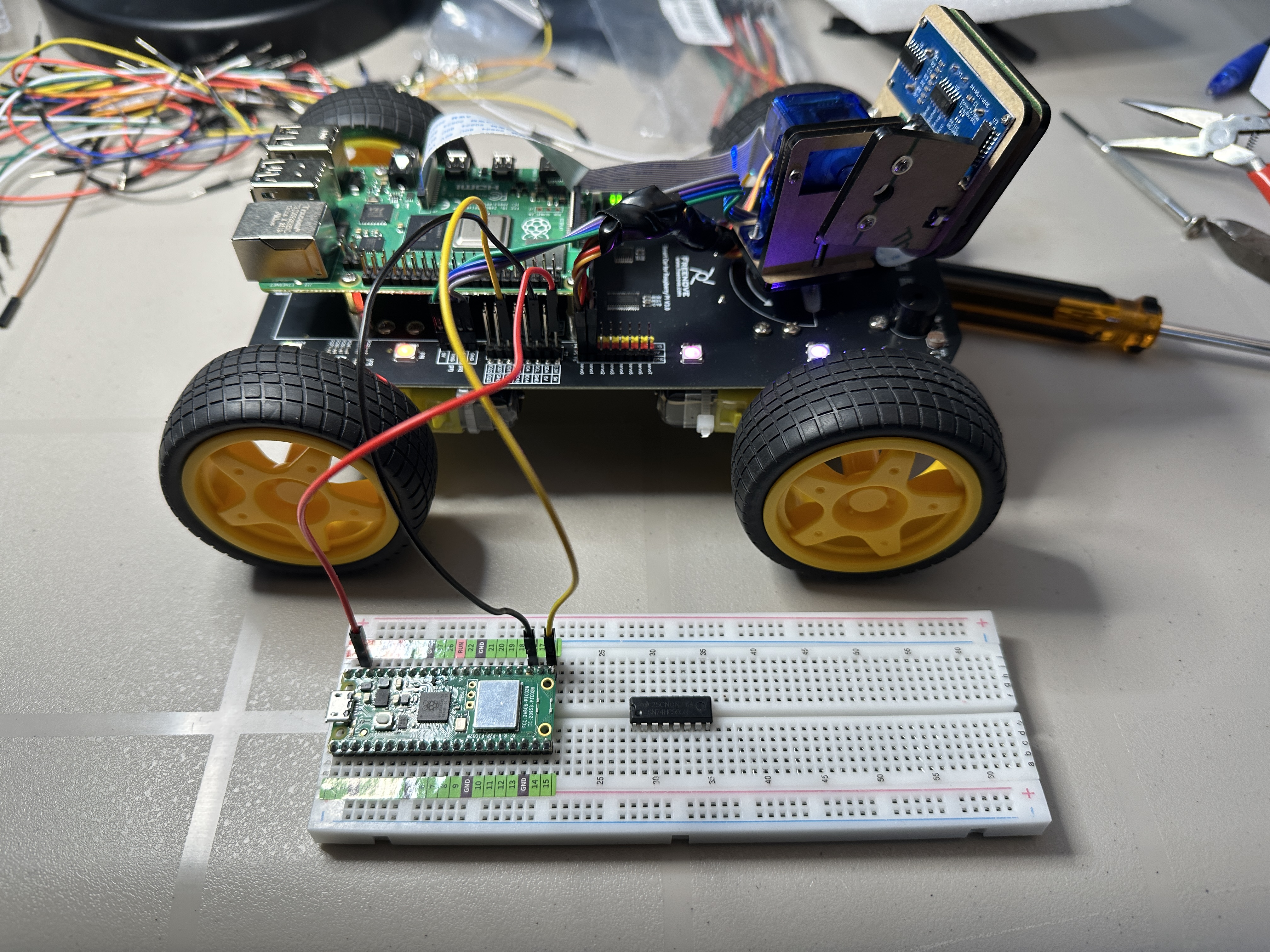
Description
While working on the Freenove 4WD Smart Car, I ran into an issue controlling the onboard WS2812 (NeoPixel) LEDs using a Raspberry Pi 5. The LEDs would partially light or behave unpredictably, suggesting a timing-related problem rather than a hardware fault.
After learning more about how WS2812 LEDs work — specifically their strict 800 kHz pulse-width timing requirements — I experimented with using a Raspberry Pi Pico 2 W instead of the Raspberry Pi 5.
I disconnected the Pi 5 from the LED data line (GPIO10 on PCB V2.0) and connected the Pico directly to the WS2812 data input. Using the Pico’s PIO (Programmable I/O) hardware, I was able to generate precise timing signals and successfully control all 8 LEDs, including smooth animations such as rainbow effects and a Knight Rider scanner pattern.
This experiment proved that:
- The LED hardware and wiring were functioning correctly.
- The issue was not power-related.
- The problem was due to timing sensitivity when generating the WS2812 signal from Linux on the Raspberry Pi 5.
By offloading LED control to the Pico — a microcontroller designed for deterministic, real-time signal generation — the LEDs operated flawlessly.
Use a microcontroller for precise timing tasks, and a Linux-based system for high-level control and networking.
The Pico could be used as a dedicated LED coprocessor for the 4WD car.
Description
Counts in hexadecimal (0–F) and displays each value on a single 7-segment LED using a 74HC595 shift register. The shift register allows the Raspberry Pi Pico 2 W to control the display using only three GPIO pins by converting serial data into parallel output.
The decimal point flashes each time the counter advances, providing a visual indicator of the update timing. This project demonstrates how a shift register can expand the number of outputs available from the microcontroller while maintaining simple wiring.
Features
- Hexadecimal counter displaying digits 0–F
- Single 7-segment LED display driven through a 74HC595 shift register
- Decimal point flashes on each count
- Demonstrates serial-to-parallel data conversion
- Illustrates bit-level control of a shift register
- Efficient use of GPIO pins on the Raspberry Pi Pico 2 W
Source Code
View Python source: main.py
#######
#
# Project: 7-Segment Counter with Flashing Decimal Point
# Based on common 74HC595 shift register usage patterns and
# 7-segment display encoding examples.
#
# Adapted and documented by Denis Legault
# Date:    2026-03-01
# Python File: main.py
# Hardware: Raspberry Pi Pico 2 W,
#           74HC595 Shift Register,
#           1x Common Anode 7-Segment Display
#
# Description:
# Displays hexadecimal digits (0–F) on a 7-segment display
# using a 74HC595 shift register. The decimal point (DP)
# flashes ON and OFF for each digit.
#
# Display Type:
#   Common Anode (Active LOW)
#   - 0 = Segment ON
#   - 1 = Segment OFF
#
# Bit Layout (based on wiring configuration):
#   Bit 7 → DP (Decimal Point)
#   Bit 6 → Segment A
#   Bit 5 → Segment B
#   Bit 4 → Segment C
#   Bit 3 → Segment D
#   Bit 2 → Segment E
#   Bit 1 → Segment F
#   Bit 0 → Segment G
#
# Notes:
# - Uses LSB-first shifting via 74HC595.
# - Decimal point controlled via bit mask (0x80).
#
#######

import time
from my74HC595 import Chip74HC595

# ------------------------------------------------------------
# 7-Segment Encoding Table (Hexadecimal 0–F)
# ------------------------------------------------------------
SEGMENT_MAP = [
    0xC0,  # 0
    0xF9,  # 1
    0xA4,  # 2
    0xB0,  # 3
    0x99,  # 4
    0x92,  # 5
    0x82,  # 6
    0xF8,  # 7
    0x80,  # 8
    0x90,  # 9
    0x88,  # A
    0x83,  # b
    0xC6,  # C
    0xA1,  # d
    0x86,  # E
    0x8E   # F
]


# ------------------------------------------------------------
# Decimal Point Helper (Active LOW)
# ------------------------------------------------------------
def set_dp(value, on):
    """
    Enable or disable decimal point.
    Common Anode display → active LOW.
    """
    if on:
        return value & ~0x80   # Clear bit 7 → DP ON
    else:
        return value | 0x80    # Set bit 7 → DP OFF


# Initialize 74HC595
chip = Chip74HC595(18, 20, 21)


# ------------------------------------------------------------
# Main Loop
# ------------------------------------------------------------
while True:
    for count in range(16):

        value = SEGMENT_MAP[count]

        # Display digit with DP ON
        chip.shiftOut(0, set_dp(value, True))
        time.sleep(0.5)

        # Display digit with DP OFF
        chip.shiftOut(0, set_dp(value, False))
        time.sleep(0.5)
View Python source: my74HC595.py
#######
#
# Module: 74HC595 Shift Register Driver
# Based on common 74HC595 shift register usage patterns and
# MicroPython GPIO examples.
#
# Adapted and documented by Denis Legault
# Date:    2026-03-01
# Python File: chip74hc595.py
# Hardware: Raspberry Pi Pico 2 W,
#           74HC595 8-bit shift register
#
# Description:
# Provides a simple MicroPython driver for controlling a 74HC595
# serial-in / parallel-out shift register using GPIO pins.
#
# The class allows:
# - Shifting out 8-bit values (MSB-first or LSB-first)
# - Clearing the register
# - Enabling and disabling output
#
# The 74HC595 is commonly used to expand GPIO output pins,
# allowing control of multiple LEDs or digital outputs using
# only three control lines from the Pico.
#
# 74HC595 Pin Connections:
# 14 (DS)   -> Pico GPIO18  (Serial Data)
# 12 (STCP) -> Pico GPIO20  (Storage Register Clock / Latch)
# 11 (SHCP) -> Pico GPIO21  (Shift Register Clock)
# 13 (OE)   -> Pico GPIO19  (Output Enable, active LOW)
# 16 (VCC)  -> 5V or 3.3V (depending on design)
# 8  (GND)  -> Ground (shared with Pico)
#
# Notes:
# - Outputs Q0–Q7 update only after latch (STCP) pulse.
# - OE is active LOW (LOW = outputs enabled).
# - Multiple 74HC595 chips can be daisy-chained.
#
#######

from machine import Pin


class Chip74HC595(object):
    def __init__(self, ds: int = 18, stcp: int = 20, shcp: int = 21, oe: int = 19):
        """
        Initialize 74HC595 control pins.

        :param ds:   Serial Data input (DS)
        :param stcp: Storage Register Clock (Latch)
        :param shcp: Shift Register Clock
        :param oe:   Output Enable (active LOW)
        """

        # Configure control pins as outputs
        self._ds = Pin(ds, Pin.OUT, value=0)      # Data pin
        self._shcp = Pin(shcp, Pin.OUT, value=0)  # Shift clock
        self._stcp = Pin(stcp, Pin.OUT, value=0)  # Latch clock
        self._oe = Pin(oe, Pin.OUT, value=0)      # Output enable

        # Enable outputs by default
        self.enable()

    # --------------------------------------------------------
    # Shift out 8 bits of data
    # --------------------------------------------------------
    def shiftOut(self, direction, data):
        """
        Shift out one byte (8 bits) to the register.

        :param direction: True = MSB first, False = LSB first
        :param data:      8-bit integer value (0–255)
        """

        # Prepare clocks
        self._shcp.on()
        self._stcp.on()

        # MSB first
        if direction:
            for i in range(8):
                bit = data << i
                bit = bit & 0x80

                if bit == 0x80:
                    self._ds.on()
                else:
                    self._ds.off()

                self._shift_bit()

            self._send_data()

        # LSB first
        if not direction:
            for i in range(8):
                bit = data >> i
                bit = bit & 0x01

                if bit == 0x01:
                    self._ds.on()
                else:
                    self._ds.off()

                self._shift_bit()

            self._send_data()

    # --------------------------------------------------------
    # Clear all outputs
    # --------------------------------------------------------
    def clear(self):
        """
        Clear the shift register (all outputs LOW).
        """
        for i in range(8):
            self._ds.off()
            self._shift_bit()

        self._send_data()
        self.enable()

    # --------------------------------------------------------
    # Pulse shift clock (SHCP)
    # --------------------------------------------------------
    def _shift_bit(self):
        """
        Clock a single bit into the shift register.
        """
        self._shcp.off()
        self._shcp.on()

    # --------------------------------------------------------
    # Pulse latch clock (STCP)
    # --------------------------------------------------------
    def _send_data(self):
        """
        Latch shifted data to output pins Q0–Q7.
        """
        self._stcp.off()
        self._stcp.on()

    # --------------------------------------------------------
    # Output Enable Control
    # --------------------------------------------------------
    def disable(self):
        """
        Disable outputs (OE HIGH).
        """
        self._oe.on()

    def enable(self):
        """
        Enable outputs (OE LOW).
        """
        self._oe.off()
Description
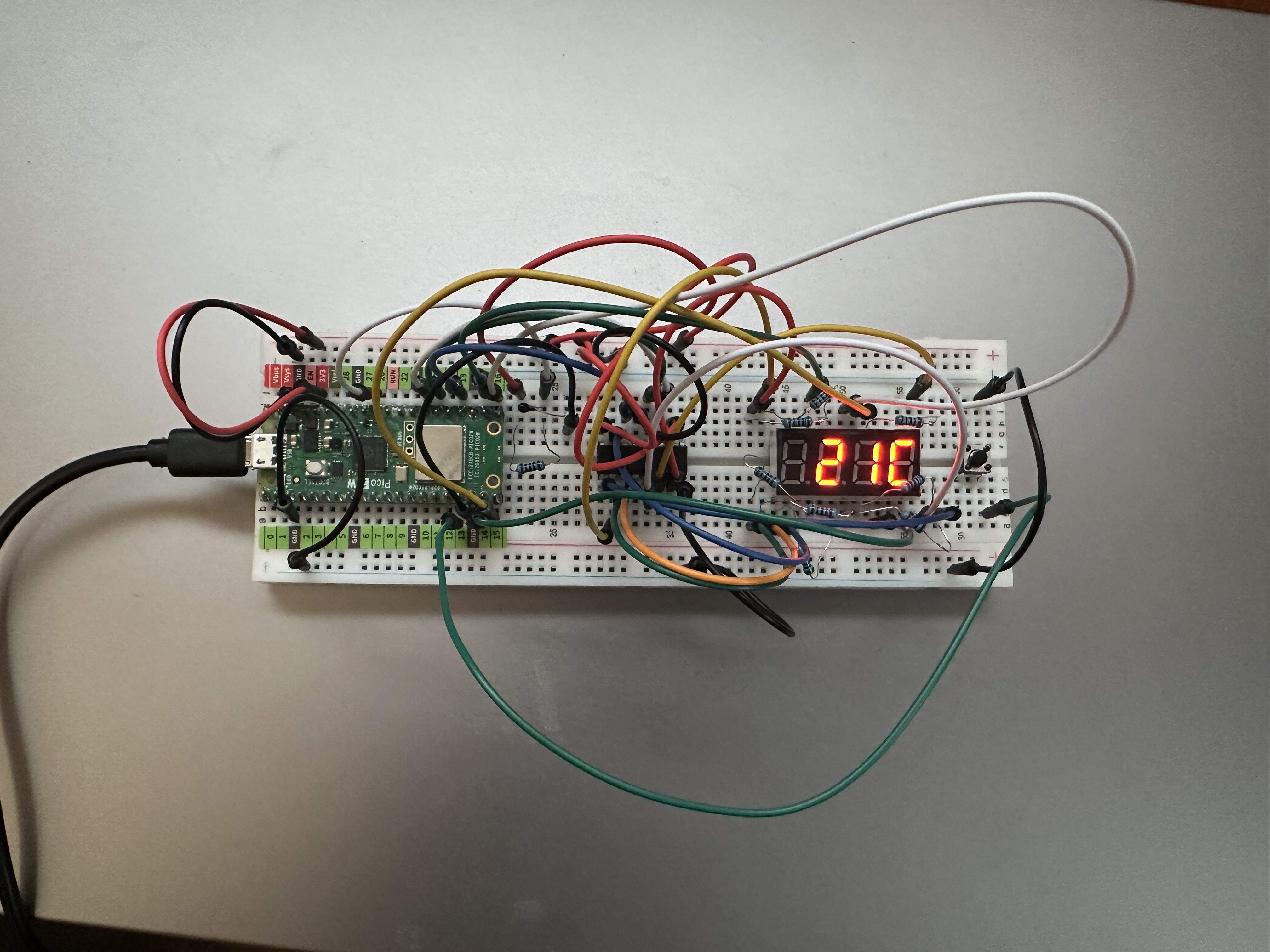
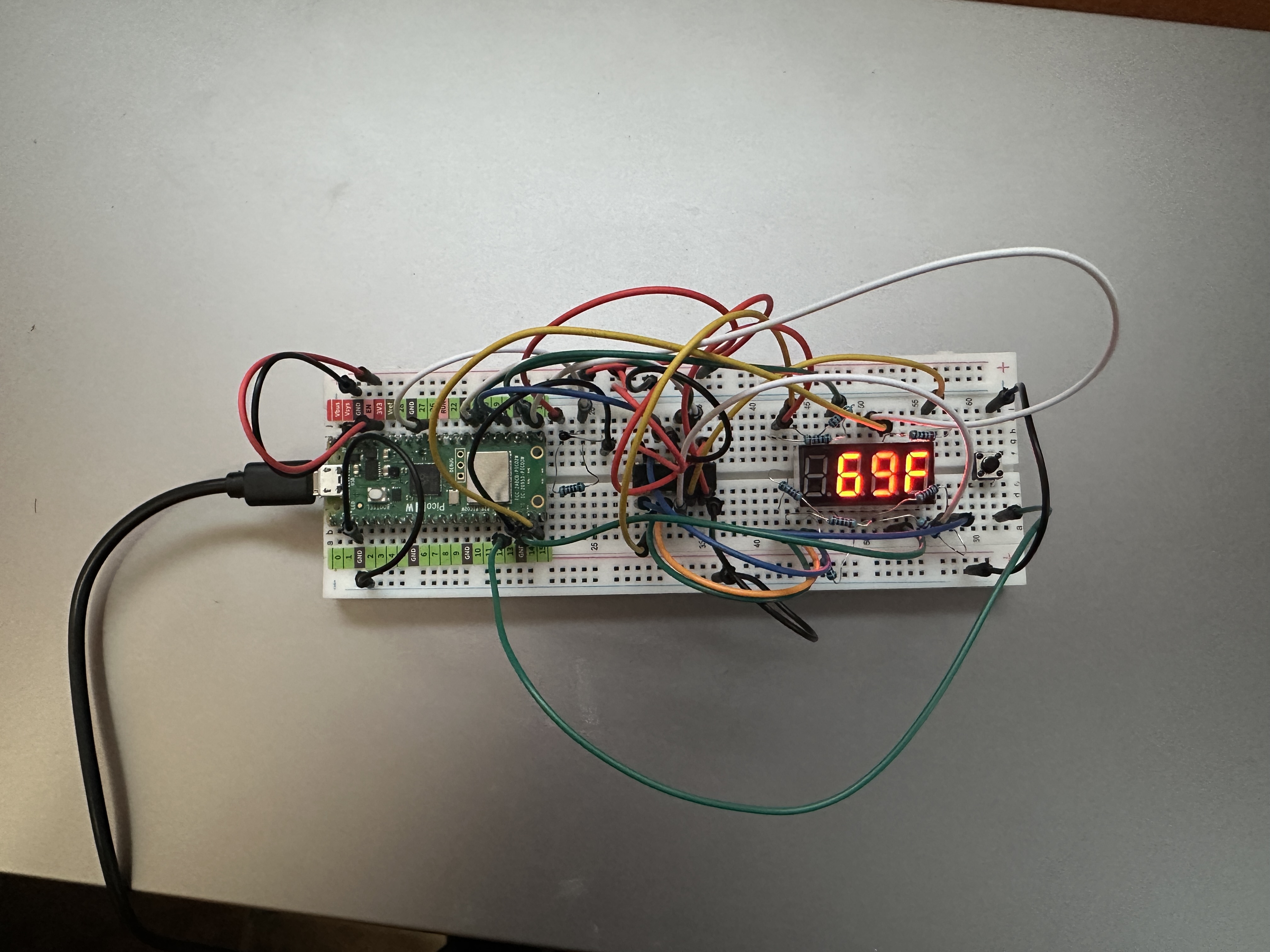
Reads temperature from a thermistor using ADC GPIO26. The temperature is calculated in Celsius using the Beta equation and displayed on a multiplexed 4-digit 7-segment display.
A push button connected to GPIO13 toggles between Celsius and Fahrenheit. The selected unit is saved to flash memory and automatically restored when the system reboots.
Features
- Clean non-blocking firmware architecture
- Celsius/Fahrenheit toggle button (one toggle per press)
- Exponential Moving Average (EMA) smoothing for stable readings
- Flash storage of temperature unit preference
- No leading zeros in display output
- Range clamping for display safety
Monitoring Pico CPU Temperature
The Raspberry Pi Pico 2 includes an internal temperature sensor that can be read using the ADC. By making a small change in the code, the project can display the CPU temperature instead of the room temperature measured by the thermistor.
Original code reading the thermistor:
adc = ADC(26) # ThermistorModified code reading the internal CPU temperature sensor:
adc = ADC(4) # Internal temperature sensorWith this change, the display shows the temperature of the Pico’s processor instead of the ambient room temperature. When running this program continuously, the CPU temperature typically stabilized around 25–26°C.
Source Code
View Python source: main.py
#######
#
# Project: Thermistor Temperature Display (°C / °F)
# Author:  Denis Legault
# Date:    2026-03-03
# Python File: main.py
# Hardware: Raspberry Pi Pico 2 W,
#           Thermistor connected to GPIO26 (ADC0),
#           Push Button on GPIO13 (to GND),
#           74HC595 Shift Register,
#           4-Digit Common Anode 7-Segment Display
#
# Description:
# Reads temperature from a thermistor using ADC GPIO26.
# Calculates temperature in Celsius using the Beta equation.
# Displays temperature on a multiplexed 4-digit 7-segment display.
#
# A push button on GPIO13 toggles between Celsius and Fahrenheit.
# The selected unit is saved to flash and restored on reboot.
#
# Features:
# - Clean non-blocking architecture
# - C/F toggle button (one toggle per press)
# - Exponential Moving Average (EMA) smoothing
# - Flash preference saving
# - No leading zeros
# - Range clamping for display safety
#
# Display Type:
#   Common Anode (Active LOW)
#
#######

import time
import math
from machine import Pin, ADC
from my74HC595 import Chip74HC595


# --------------------------------------------------------------
# Debug flag
# --------------------------------------------------------------
DEBUG = False


# --------------------------------------------------------------
# Flash Preference Handling
# --------------------------------------------------------------
def load_unit_preference():
    try:
        with open("unit.cfg", "r") as f:
            value = f.read().strip()
            return True if value == "F" else False
    except:
        return False  # Default to Celsius


def save_unit_preference(use_fahrenheit):
    with open("unit.cfg", "w") as f:
        f.write("F" if use_fahrenheit else "C")


# Load saved preference
use_fahrenheit = load_unit_preference()


# --------------------------------------------------------------
# Hardware Setup
# --------------------------------------------------------------
adc = ADC(26)
chip = Chip74HC595(18, 20, 21)
comPin = [17, 16, 15, 14]
button = Pin(13, Pin.IN, Pin.PULL_UP)


# --------------------------------------------------------------
# 7-Segment Encoding Table (Active LOW)
# --------------------------------------------------------------
SEGMENT_MAP = [
    0xC0, 0xF9, 0xA4, 0xB0,
    0x99, 0x92, 0x82, 0xF8,
    0x80, 0x90, 0x88, 0x83,
    0xC6, 0xA1, 0x86, 0x8E
]

C_INDEX = 12
F_INDEX = 15
MINUS = 0xFE
BLANK = 0xFF


# --------------------------------------------------------------
# Multiplex Display
# --------------------------------------------------------------
def led_display(digits):
    for i in range(4):
        digit_pin = Pin(comPin[i], Pin.OUT)
        chip.shiftOut(0, digits[i])
        digit_pin.value(1)
        time.sleep_ms(1)
        digit_pin.value(0)


# --------------------------------------------------------------
# Format Temperature
# --------------------------------------------------------------
def format_temperature(temp_value, unit_index, use_fahrenheit):

    if use_fahrenheit:
        if temp_value >= 100:
            return [
                SEGMENT_MAP[temp_value // 100],
                SEGMENT_MAP[(temp_value // 10) % 10],
                SEGMENT_MAP[temp_value % 10],
                SEGMENT_MAP[unit_index]
            ]
        elif temp_value >= 10:
            return [
                BLANK,
                SEGMENT_MAP[temp_value // 10],
                SEGMENT_MAP[temp_value % 10],
                SEGMENT_MAP[unit_index]
            ]
        else:
            return [
                BLANK,
                BLANK,
                SEGMENT_MAP[temp_value],
                SEGMENT_MAP[unit_index]
            ]
    else:
        if temp_value < 0:
            abs_temp = abs(temp_value)
            if abs_temp >= 10:
                return [
                    MINUS,
                    SEGMENT_MAP[abs_temp // 10],
                    SEGMENT_MAP[abs_temp % 10],
                    SEGMENT_MAP[unit_index]
                ]
            else:
                return [
                    BLANK,
                    MINUS,
                    SEGMENT_MAP[abs_temp],
                    SEGMENT_MAP[unit_index]
                ]
        else:
            if temp_value >= 10:
                return [
                    BLANK,
                    SEGMENT_MAP[temp_value // 10],
                    SEGMENT_MAP[temp_value % 10],
                    SEGMENT_MAP[unit_index]
                ]
            else:
                return [
                    BLANK,
                    BLANK,
                    SEGMENT_MAP[temp_value],
                    SEGMENT_MAP[unit_index]
                ]


# --------------------------------------------------------------
# EMA Smoothing
# --------------------------------------------------------------
alpha = 0.1
filtered = None


# --------------------------------------------------------------
# Button State Tracking
# --------------------------------------------------------------
button_pressed = False


# --------------------------------------------------------------
# Temperature Update Timing
# --------------------------------------------------------------
last_temp_update = 0
TEMP_UPDATE_MS = 1000
digits = [BLANK, BLANK, BLANK, BLANK]


# --------------------------------------------------------------
# Main Loop
# --------------------------------------------------------------
while True:

    # --------------------------
    # Button Toggle Logic
    # --------------------------
    if button.value() == 0 and not button_pressed:
        use_fahrenheit = not use_fahrenheit
        save_unit_preference(use_fahrenheit)
        button_pressed = True

    if button.value() == 1:
        button_pressed = False


    # --------------------------
    # Temperature Update (1 sec)
    # --------------------------
    now = time.ticks_ms()

    if time.ticks_diff(now, last_temp_update) > TEMP_UPDATE_MS:

        raw = adc.read_u16()

        if filtered is None:
            filtered = raw
        else:
            filtered = alpha * raw + (1 - alpha) * filtered

        adcValue = int(filtered)

        voltage = adcValue / 65535.0 * 3.3
        Rt = 10 * voltage / (3.3 - voltage)

        tempK = (1 / (1 / (273.15 + 25) +
                      (math.log(Rt / 10)) / 3950))

        tempC = round(tempK - 273.15)

        if use_fahrenheit:
            tempDisplay = int(tempC * 9 / 5 + 32)
            tempDisplay = max(0, min(999, tempDisplay))
            unit_index = F_INDEX
        else:
            tempDisplay = max(-99, min(99, tempC))
            unit_index = C_INDEX

        if DEBUG:
            print("Temperature:",
                  tempDisplay,
                  "F" if use_fahrenheit else "C")

        digits = format_temperature(
            tempDisplay,
            unit_index,
            use_fahrenheit
        )

        last_temp_update = now

    # --------------------------
    # Continuous Display Refresh
    # --------------------------
    led_display(digits)
Library my74HC595.py required (see code above)
Description
Press button on the right to switch between Celsius and Fahrenheit.
Description
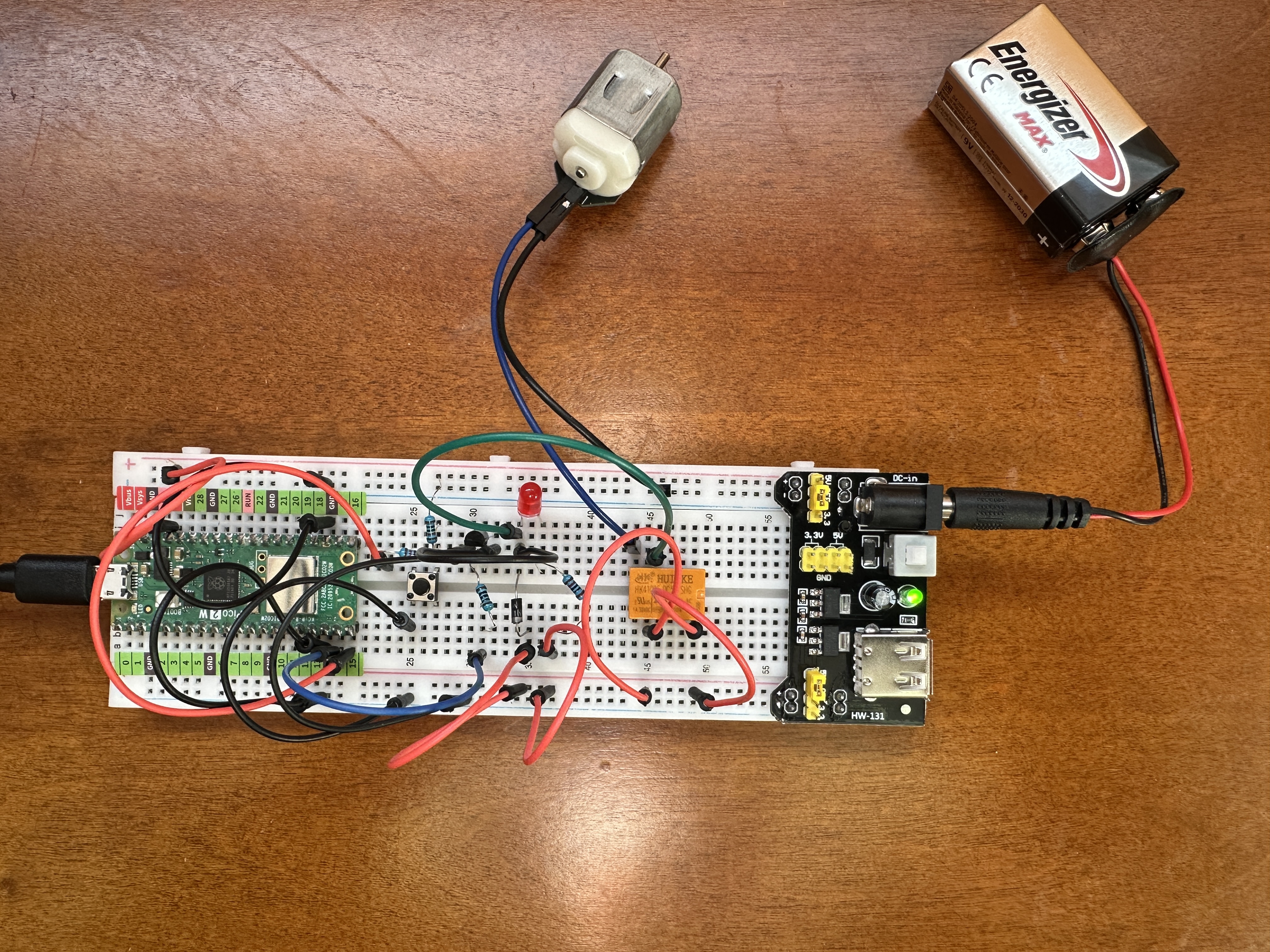
Demonstrates controlling a DC motor using a relay module and a push button connected to a Raspberry Pi Pico 2 W. Each time the button is pressed, the relay toggles between ON and OFF, starting or stopping the motor.
The relay allows the Pico to safely control a motor powered from an external 9V battery while keeping the high-current motor circuit electrically isolated from the microcontroller. A short software debounce delay is used to prevent false triggering caused by mechanical switch bounce.
At startup the relay is forced OFF to ensure the motor does not accidentally start when the system powers up or resets.
Features
- Push button toggles motor ON and OFF
- Relay module isolates motor power from the Pico
- Software debounce improves button reliability
- Motor powered from external 9V battery supply
- Relay forced OFF at startup for safety
- Designed to run automatically when saved as
main.py
Hardware
- Raspberry Pi Pico 2 W
- Relay module connected to GPIO14
- Push button connected to GPIO15
- DC motor powered by external 9V battery
- Breadboard power module
Safety Note
A flyback diode should be installed across the motor terminals to protect the relay contacts and electronics from voltage spikes generated when the motor is switched off.
Motor + ----|>|---- Motor -The diode's cathode (striped end) connects to the motor positive terminal, and the anode connects to the motor negative terminal.
Source Code
View Python source: main.py
#######
#
# Project: Motor Control with Relay and Push Button
# Based on open-source examples from the Raspberry Pi Foundation
# and MicroPython community.
#
# Adapted and documented by Denis Legault
# Date:    2026-03-08
# Python File: main.py
# Hardware: Raspberry Pi Pico 2 W,
#           Relay Module connected to GPIO14,
#           Push Button connected to GPIO15,
#           DC Motor powered from external 9V battery
#           Breadboard power module
#
# Description:
# Demonstrates controlling a DC motor using a relay module and a push
# button connected to a Raspberry Pi Pico 2 W. Each time the button is
# pressed, the relay toggles between ON and OFF, starting or stopping
# the motor.
#
# At startup the relay is forced OFF to ensure the motor does not
# accidentally start when the system powers up or resets.
#
# The relay isolates the Pico from the higher motor voltage supplied
# by the external battery. A short software debounce delay is used to
# prevent false triggering caused by mechanical button bounce.
#
# GPIO Pin Connections:
# Relay IN   -> GPIO14
# Relay VCC  -> 5V or 3.3V (depending on relay module)
# Relay GND  -> GND
#
# Button     -> GPIO15
# Other side -> GND
#
# External Power:
# 9V Battery -> Breadboard power module
# Motor +    -> Relay COM
# Motor -    -> Battery GND
# Battery +  -> Relay NO
#
# When the relay closes, the motor receives power from the battery.
#
# Safety Note (Flyback Diode):
# A flyback diode should be placed across the motor terminals to
# protect the relay contacts and electronics from voltage spikes
# generated when the motor is switched OFF.
#
# Diode connection:
# Motor + ----|>|---- Motor -
#
# The diode's cathode (striped end) connects to the motor positive
# terminal, and the anode connects to the motor negative terminal.
#
# Notes:
# - Relay default state is forced OFF at startup.
# - The relay provides electrical isolation between the Pico and motor.
# - Button uses polling with simple software debounce.
# - The motor runs until the button is pressed again.
# - Saved as main.py to auto-run on power-up.
#
#######

import time
from machine import Pin

# --------------------------------------------------------------
# Hardware Setup
# --------------------------------------------------------------

# Relay output pin controlling motor power
relay = Pin(14, Pin.OUT)

# Force relay OFF at startup (motor stopped)
relay.value(0)

# Push button input pin
button = Pin(15, Pin.IN)


# --------------------------------------------------------------
# Relay Toggle Function
# --------------------------------------------------------------
# Reverses the current relay state.
# If relay is ON → turn OFF
# If relay is OFF → turn ON
# --------------------------------------------------------------

def reverseRelay():
    if relay.value():
        relay.value(0)
    else:
        relay.value(1)


# --------------------------------------------------------------
# Main Loop
# --------------------------------------------------------------
# Continuously checks the button state.
# When the button is pressed:
#   1. Apply debounce delay
#   2. Toggle the relay
#   3. Wait until the button is released
# --------------------------------------------------------------

while True:

    # Detect button press (LOW when pressed)
    if not button.value():

        # Debounce delay
        time.sleep_ms(20)

        # Confirm button still pressed
        if not button.value():

            # Toggle relay state (start/stop motor)
            reverseRelay()

            # Wait until button is released
            while not button.value():
                time.sleep_ms(20)
Description
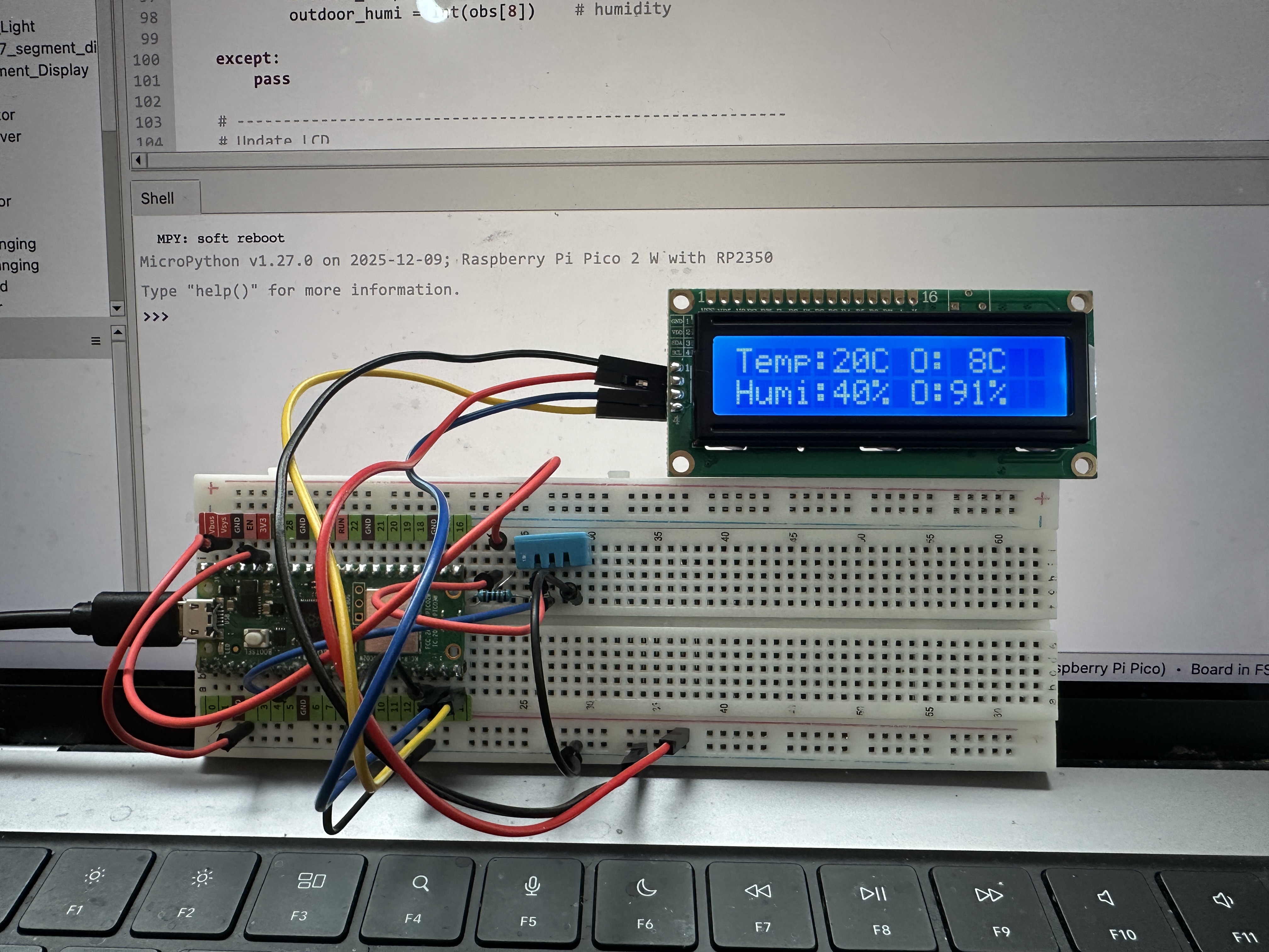
Creates a small indoor/outdoor weather console using a Raspberry Pi Pico 2 W, a DHT11 temperature and humidity sensor, and a 16x2 LCD display connected through an I2C interface. Indoor temperature and humidity are measured locally using the DHT11 sensor.
Outdoor weather data is received from a Tempest Weather Station using
local UDP broadcast packets. The Pico connects to WiFi and listens
on UDP port 50222 for obs_st observation packets
transmitted by the Tempest hub.
Temperature, humidity, wind speed, and rainfall values are extracted from the packets and displayed on the LCD. The display automatically rotates between two screens showing temperature/humidity and wind/rain information.
Features
- Indoor temperature and humidity using a DHT11 sensor
- Outdoor weather data from a Tempest Weather Station
- WiFi connection with UDP packet reception
- Automatic decoding of Tempest
obs_stobservation packets - Two rotating LCD screens displaying weather information
- Wind speed conversion from m/s to km/h
- Designed to run automatically when saved as
main.py
Hardware
- Raspberry Pi Pico 2 W
- HD44780-compatible 16x2 LCD display with PCF8574 I2C backpack
- DHT11 temperature and humidity sensor
- Tempest Weather Station
GPIO Connections
- DHT11 DATA → GPIO5
- LCD SDA → GPIO14
- LCD SCL → GPIO15
- DHT11 VCC → 3.3V
- DHT11 GND → GND
Network Requirements
The Tempest hub must have Local Broadcast enabled in the Tempest mobile app. The Pico must be connected to the same WiFi network as the hub to receive UDP packets.
LCD Display Layout
Screen 1 – Temperature and Humidity
Temp:21C O:8C
Humi:39% O:90%
Screen 2 – Wind and Rain
Wind: 8 km/h
Rain: 0.2 mm
Libraries Used
mydh.py– DHT11/DHT22 sensor driverI2C_LCD.py– I2C LCD driverLCD_API.py– HD44780 display API
Source Code
View Python source: main.py
#######
#
# Project: Indoor / Outdoor Weather Console (DHT11 + Tempest)
# Based on open-source MicroPython examples for DHT sensors,
# I2C LCD displays, and Tempest UDP broadcast packets.
#
# Adapted and documented by Denis Legault
# Date:    2026-03-16
# Python File: main.py
# Hardware: Raspberry Pi Pico 2 W,
#           HD44780-compatible 16x2 LCD with PCF8574 I2C backpack,
#           DHT11 Temperature and Humidity Sensor,
#           Tempest Weather Station (local UDP broadcast)
#
# Description:
# Creates a small indoor/outdoor weather console using a 16x2 LCD.
# Indoor temperature and humidity are measured using a DHT11 sensor
# connected directly to the Pico. Outdoor weather data is received
# from a Tempest Weather Station using local UDP broadcast packets.
#
# The Pico connects to WiFi and listens for Tempest "obs_st"
# observation packets on UDP port 50222. Temperature, humidity,
# wind speed, and rainfall values are extracted and displayed.
#
# The display rotates between two screens every few seconds:
#
# Screen 1 (Temperature / Humidity)
#   Temp:21C O:8C
#   Humi:39% O:90%
#
# Screen 2 (Wind / Rain)
#   Wind: 8 km/h
#   Rain: 0.2 mm
#
# Indoor readings come from the DHT11 sensor and outdoor readings
# are received from the Tempest weather station.
#
# GPIO Pin Connections:
#
# DHT11 Sensor
# DATA -> GPIO5
# VCC  -> 3.3V
# GND  -> GND
#
# LCD I2C
# SDA -> GPIO14
# SCL -> GPIO15
# VCC -> 5V or 3.3V (depending on module)
# GND -> GND
#
# Network Requirements:
#
# - Tempest Hub must have Local Broadcast enabled.
# - Pico must connect to the same WiFi network.
# - Tempest broadcasts observation packets on UDP port 50222.
#
# Libraries Required:
#
# - mydht.py
# - I2C_LCD.py
# - LCD_API.py
#
# Notes:
#
# - Wind speed is converted from m/s to km/h.
# - Rainfall value is read directly from Tempest packet data.
# - Display automatically rotates between two weather screens.
# - Saved as main.py to auto-run on power-up.
#
#######

import time
import network
import socket
import json

from machine import I2C, Pin
from I2C_LCD import I2CLcd
from mydht import DHT11


# --------------------------------------------------------------
# Indoor Sensor Initialization (DHT11)
# --------------------------------------------------------------

dht = DHT11(Pin(5))

indoor_temp = 0
indoor_humi = 0


# --------------------------------------------------------------
# LCD Initialization
# --------------------------------------------------------------

i2c = I2C(1, sda=Pin(14), scl=Pin(15), freq=400000)
devices = i2c.scan()

lcd = I2CLcd(i2c, devices[0], 2, 16)

lcd.clear()
lcd.putstr("Weather Console")
time.sleep(2)
lcd.clear()


# --------------------------------------------------------------
# WiFi Connection
# --------------------------------------------------------------

SSID = "My SSID"
PASSWORD = "Wifi Password"

wlan = network.WLAN(network.STA_IF)
wlan.active(True)
wlan.connect(SSID, PASSWORD)

print("Connecting to WiFi...")

while not wlan.isconnected():
    time.sleep(1)

print("Connected:", wlan.ifconfig())


# --------------------------------------------------------------
# Tempest UDP Listener
# --------------------------------------------------------------

UDP_PORT = 50222

sock = socket.socket(socket.AF_INET, socket.SOCK_DGRAM)
sock.bind(("0.0.0.0", UDP_PORT))

# Non-blocking socket so program continues running
sock.setblocking(False)

print("Listening for Tempest packets...")


# --------------------------------------------------------------
# Outdoor Weather Variables
# --------------------------------------------------------------

outdoor_temp = 0
outdoor_humi = 0
wind_kmh = 0
rain_mm = 0


# --------------------------------------------------------------
# Display Screen Rotation
# --------------------------------------------------------------

screen = 0
last_screen_change = time.time()


# --------------------------------------------------------------
# Main Loop
# --------------------------------------------------------------

while True:

    # ----------------------------------------------------------
    # Read Indoor Sensor
    # ----------------------------------------------------------

    try:
        temp = dht.temperature
        humi = dht.humidity

        if temp is not None and humi is not None:
           indoor_temp = int(temp)
           indoor_humi = int(humi)

    except Exception:
        # keep previous values if read fails
        pass

    # For debugging, replace with:
    # except Exception as e:
    #    print("DHT error:", e)

    # ----------------------------------------------------------
    # Receive Tempest Weather Packets
    # ----------------------------------------------------------

    try:
        data, addr = sock.recvfrom(1024)

        packet = json.loads(data)

        # Only process observation packets
        if packet["type"] == "obs_st":

            obs = packet["obs"][0]

            outdoor_temp = int(obs[7])
            outdoor_humi = int(obs[8])

            # Convert wind speed from m/s to km/h
            wind_kmh = int(obs[2] * 3.6)

            # Rain accumulation
            rain_mm = obs[12]

    except:
        pass


    # ----------------------------------------------------------
    # Rotate Display Screen Every 5 Seconds
    # ----------------------------------------------------------

    if time.time() - last_screen_change > 5:

        screen = (screen + 1) % 2
        lcd.clear()
        last_screen_change = time.time()


    # ----------------------------------------------------------
    # Screen 1 – Temperature / Humidity
    # ----------------------------------------------------------

    if screen == 0:

        lcd.move_to(0, 0)
        lcd.putstr("Temp:%2dC O:%2dC " % (indoor_temp, outdoor_temp))

        lcd.move_to(0, 1)
        lcd.putstr("Humi:%2d%% O:%2d%% " % (indoor_humi, outdoor_humi))


    # ----------------------------------------------------------
    # Screen 2 – Wind / Rain
    # ----------------------------------------------------------

    else:

        lcd.move_to(0, 0)
        lcd.putstr("Wind:%3d km/h  " % wind_kmh)

        lcd.move_to(0, 1)
        lcd.putstr("Rain:%4.1f mm " % rain_mm)


    time.sleep(1)
View Python source: mydht.py
#######
#
# Module: DHT11 / DHT22 Temperature and Humidity Sensor Driver
# Based on open-source MicroPython DHT sensor implementations.
#
# Adapted and documented by Denis Legault
# Date: 2026-03-17
# Python File: mydht.py
# Hardware: Raspberry Pi Pico / Pico 2 W,
#           DHT11 or DHT22 Temperature and Humidity Sensor
#
# Description:
# Provides a MicroPython driver for reading temperature and humidity
# from DHT11 and DHT22 digital sensors. The driver communicates with
# the sensor using a single GPIO pin and measures precise pulse timing
# to decode the transmitted data.
#
# The sensor sends 40 bits of data containing humidity, temperature,
# and a checksum. This module captures pulse timings, converts them
# into binary values, and validates the checksum before returning
# sensor readings.
#
# Features:
# - Supports both DHT11 and DHT22 sensors
# - Reads temperature and humidity values
# - Automatic timing control between measurements
# - Pulse timing capture for decoding sensor data
# - Checksum validation for data integrity
# - Automatic retry on read failure for improved reliability
#
# Notes:
# - DHT11 minimum interval ~1 second
# - DHT22 minimum interval ~2 seconds
# - Uses microsecond timing to decode the digital signal
# - Returns last valid reading if a read fails
#
# GPIO Connection:
# DATA -> Pico GPIO pin (example GPIO16)
# VCC  -> 3.3V
# GND  -> GND
#
# A 10kΩ pull-up resistor between DATA and VCC is recommended.
#
# Usage example:
#   from mydht import DHT11
#   dht = DHT11(Pin(5))
#
#   from mydht import DHT22
#   dht = DHT22(Pin(5))
#
#######

import array
import micropython
import utime
from machine import Pin
from micropython import const


# --------------------------------------------------------------
# Custom Exceptions
# --------------------------------------------------------------

class InvalidChecksum(Exception):
    pass


class InvalidPulseCount(Exception):
    pass


# --------------------------------------------------------------
# Timing and Protocol Constants
# --------------------------------------------------------------

MAX_UNCHANGED = const(100)          # Timeout for pulse capture loop
MIN_INTERVAL_US_DHT11 = const(1000000)   # 1 second minimum interval
MIN_INTERVAL_US_DHT22 = const(2000000)   # 2 seconds minimum interval

HIGH_LEVEL = const(50)              # Threshold to distinguish 0 vs 1
EXPECTED_PULSES = const(84)         # Expected number of transitions


# --------------------------------------------------------------
# Base Class (Shared Logic)
# --------------------------------------------------------------

class DHTBase:
    """
    Base class for DHT sensors (shared pulse timing logic).
    """

    def __init__(self, pin, min_interval):
        # GPIO pin used for sensor communication
        self._pin = pin

        # Last successful measurement timestamp
        self._last_measure = utime.ticks_us()

        # Cached values (None until first valid reading)
        self._temperature = None
        self._humidity = None

        # Minimum interval between reads (sensor-specific)
        self._min_interval = min_interval


    def measure(self):
        """
        Initiates a measurement cycle and updates sensor values.
        Includes automatic retry for improved reliability.
        """

        current_ticks = utime.ticks_us()

        # Respect minimum interval between reads
        if utime.ticks_diff(current_ticks, self._last_measure) < self._min_interval and (
            self._temperature is not None or self._humidity is not None
        ):
            return

        # Try reading sensor (with one retry on failure)
        for _ in range(2):

            try:
                # Send start signal to sensor
                self._send_init_signal()

                # Capture pulse timings
                pulses = self._capture_pulses()

                # Convert pulses into data bytes
                buffer = self._convert_pulses_to_buffer(pulses)

                # Validate checksum
                self._verify_checksum(buffer)

                # Decode sensor-specific values
                self._decode(buffer)

                # Update timestamp only on success
                self._last_measure = utime.ticks_us()

                return

            except (InvalidChecksum, InvalidPulseCount):
                # Retry once if read fails
                continue


    @property
    def humidity(self):
        """Return humidity value (%)"""
        self.measure()
        return self._humidity


    @property
    def temperature(self):
        """Return temperature value (°C)"""
        self.measure()
        return self._temperature


    # ----------------------------------------------------------
    # Shared Low-Level Functions
    # ----------------------------------------------------------

    def _send_init_signal(self):
        """
        Sends the start signal required by the DHT protocol.
        """

        self._pin.init(Pin.OUT, Pin.PULL_DOWN)

        # Pull line HIGH briefly
        self._pin.value(1)
        utime.sleep_ms(50)

        # Pull line LOW to initiate communication
        self._pin.value(0)
        utime.sleep_ms(18)


    @micropython.native
    def _capture_pulses(self):
        """
        Captures pulse timing transitions sent by the sensor.
        Timing accuracy is critical for correct decoding.
        """

        pin = self._pin
        pin.init(Pin.IN, Pin.PULL_UP)

        val = 1
        idx = 0
        transitions = bytearray(EXPECTED_PULSES)

        unchanged = 0
        timestamp = utime.ticks_us()

        while unchanged < MAX_UNCHANGED:

            if val != pin.value():

                if idx >= EXPECTED_PULSES:
                    raise InvalidPulseCount(
                        "Got more than {} pulses".format(EXPECTED_PULSES)
                    )

                now = utime.ticks_us()

                transitions[idx] = now - timestamp
                timestamp = now
                idx += 1

                val = 1 - val
                unchanged = 0

            else:
                unchanged += 1

        # Return pin to safe state
        pin.init(Pin.OUT, Pin.PULL_DOWN)

        if idx != EXPECTED_PULSES:
            raise InvalidPulseCount(
                "Expected {} but got {} pulses".format(EXPECTED_PULSES, idx)
            )

        # Skip first 4 transitions (sensor response preamble)
        return transitions[4:]


    def _convert_pulses_to_buffer(self, pulses):
        """
        Convert captured pulse timings into 5 bytes of data.
        """

        binary = 0

        # Convert pulse widths to bits
        for idx in range(0, len(pulses), 2):
            binary = binary << 1 | int(pulses[idx] > HIGH_LEVEL)

        buffer = array.array("B")

        # Split 40-bit value into 5 bytes
        for shift in range(4, -1, -1):
            buffer.append(binary >> shift * 8 & 0xFF)

        return buffer


    def _verify_checksum(self, buffer):
        """
        Validate sensor data using checksum.
        """

        checksum = 0

        for buf in buffer[0:4]:
            checksum += buf

        if checksum & 0xFF != buffer[4]:
            raise InvalidChecksum()


    def _decode(self, buffer):
        """
        Implemented by subclasses (DHT11 / DHT22).
        """
        raise NotImplementedError


# --------------------------------------------------------------
# DHT11 Implementation
# --------------------------------------------------------------

class DHT11(DHTBase):
    """
    Driver for DHT11 sensor.
    """

    def __init__(self, pin):
        super().__init__(pin, MIN_INTERVAL_US_DHT11)


    def _decode(self, buffer):
        """
        Decode DHT11 data format (integer values).
        """

        self._humidity = buffer[0] + buffer[1] / 10
        self._temperature = buffer[2] + buffer[3] / 10


# --------------------------------------------------------------
# DHT22 Implementation
# --------------------------------------------------------------

class DHT22(DHTBase):
    """
    Driver for DHT22 sensor.
    """

    def __init__(self, pin):
        super().__init__(pin, MIN_INTERVAL_US_DHT22)


    def _decode(self, buffer):
        """
        Decode DHT22 data format (16-bit values with decimals).
        """

        humidity_raw = (buffer[0] << 8) | buffer[1]
        temperature_raw = (buffer[2] << 8) | buffer[3]

        # Convert humidity (scale by 10)
        self._humidity = humidity_raw / 10

        # Handle negative temperature values
        if temperature_raw & 0x8000:
            temperature_raw = -(temperature_raw & 0x7FFF)

        self._temperature = temperature_raw / 10
View Python source: I2C_LCD.py
#######
#
# Module: I2C LCD Driver using PCF8574
# Based on open-source I2C LCD examples from the MicroPython community.
#
# Adapted and documented by Denis Legault
# Date: 2026-03-15
# Python File: I2C_LCD.py
# Hardware: Raspberry Pi Pico / Pico 2 W,
#           HD44780-compatible LCD with PCF8574 I2C backpack
#
# Description:
# Provides an I2C interface driver for character LCD displays that use
# the HD44780 controller together with a PCF8574 I/O expander.
#
# The PCF8574 converts I2C communication into the parallel signals
# required by the LCD controller. This reduces the number of GPIO pins
# needed from the microcontroller to only two (SDA and SCL).
#
# The module defines an I2CLcd class that extends the LcdApi base class.
# It implements the hardware abstraction layer (HAL) methods required
# by LcdApi to communicate with the display.
#
# Features:
# - LCD initialization in 4-bit mode
# - Command and data transmission over I2C
# - Backlight control
# - Compatible with 16x2 and 20x4 LCD displays
#
# Notes:
# - Uses I2C communication through the PCF8574 I/O expander.
# - LCD must support the HD44780 command set.
# - Requires LCD_API.py for higher-level LCD functions.
# - Typical I2C addresses: 0x27 or 0x3F depending on module.
#
#######

from LCD_API import LcdApi
from machine import I2C
from time import sleep_ms

# --------------------------------------------------------------
# Bit masks used to control the LCD through the PCF8574 expander
# --------------------------------------------------------------
# These values map PCF8574 output bits to the LCD control lines.

MASK_RS = 0x01          # Register Select bit
MASK_RW = 0x02          # Read/Write bit
MASK_E = 0x04           # Enable bit
SHIFT_BACKLIGHT = 3     # Backlight control bit position
SHIFT_DATA = 4          # Data bits start at bit 4


class I2CLcd(LcdApi):
    """
    Implements the hardware interface required by LcdApi for LCD
    communication over I2C using a PCF8574 I/O expander.
    """

    def __init__(self, i2c, i2c_addr, num_lines, num_columns):
        # Store I2C bus and device address
        self.i2c = i2c
        self.i2c_addr = i2c_addr

        # Clear the PCF8574 outputs
        self.i2c.writeto(self.i2c_addr, bytearray([0]))

        # Allow LCD time to power up
        sleep_ms(20)

        # ------------------------------------------------------
        # LCD initialization sequence
        # ------------------------------------------------------
        # The HD44780 controller requires a specific reset
        # sequence to enter 4-bit mode.

        # Send reset command three times
        self.hal_write_init_nibble(self.LCD_FUNCTION_RESET)
        sleep_ms(5)      # Minimum delay 4.1 ms
        self.hal_write_init_nibble(self.LCD_FUNCTION_RESET)
        sleep_ms(1)
        self.hal_write_init_nibble(self.LCD_FUNCTION_RESET)
        sleep_ms(1)

        # Switch LCD into 4-bit communication mode
        self.hal_write_init_nibble(self.LCD_FUNCTION)
        sleep_ms(1)

        # Initialize the base LCD API
        LcdApi.__init__(self, num_lines, num_columns)

        # Configure LCD function settings
        cmd = self.LCD_FUNCTION
        if num_lines > 1:
            cmd |= self.LCD_FUNCTION_2LINES

        self.hal_write_command(cmd)

    def hal_write_init_nibble(self, nibble):
        """
        Writes a 4-bit initialization value to the LCD.

        This method is used only during the LCD startup sequence.
        """
        byte = ((nibble >> 4) & 0x0f) << SHIFT_DATA

        # Pulse the Enable line to latch data
        self.i2c.writeto(self.i2c_addr, bytearray([byte | MASK_E]))
        self.i2c.writeto(self.i2c_addr, bytearray([byte]))

    def hal_backlight_on(self):
        """Turn the LCD backlight ON."""
        self.i2c.writeto(self.i2c_addr, bytearray([1 << SHIFT_BACKLIGHT]))

    def hal_backlight_off(self):
        """Turn the LCD backlight OFF."""
        self.i2c.writeto(self.i2c_addr, bytearray([0]))

    def hal_write_command(self, cmd):
        """
        Sends a command byte to the LCD controller.

        Commands configure the LCD (clear display, move cursor,
        set entry mode, etc.).
        """
        # Send high nibble
        byte = ((self.backlight << SHIFT_BACKLIGHT) |
                (((cmd >> 4) & 0x0f) << SHIFT_DATA))

        self.i2c.writeto(self.i2c_addr, bytearray([byte | MASK_E]))
        self.i2c.writeto(self.i2c_addr, bytearray([byte]))

        # Send low nibble
        byte = ((self.backlight << SHIFT_BACKLIGHT) |
                ((cmd & 0x0f) << SHIFT_DATA))

        self.i2c.writeto(self.i2c_addr, bytearray([byte | MASK_E]))
        self.i2c.writeto(self.i2c_addr, bytearray([byte]))

        # Clear and Home commands require longer delay
        if cmd <= 3:
            sleep_ms(5)

    def hal_write_data(self, data):
        """
        Sends a data byte to the LCD.

        Data corresponds to ASCII characters displayed on screen.
        """
        # Send high nibble
        byte = (MASK_RS |
                (self.backlight << SHIFT_BACKLIGHT) |
                (((data >> 4) & 0x0f) << SHIFT_DATA))

        self.i2c.writeto(self.i2c_addr, bytearray([byte | MASK_E]))
        self.i2c.writeto(self.i2c_addr, bytearray([byte]))

        # Send low nibble
        byte = (MASK_RS |
                (self.backlight << SHIFT_BACKLIGHT) |
                ((data & 0x0f) << SHIFT_DATA))

        self.i2c.writeto(self.i2c_addr, bytearray([byte | MASK_E]))
        self.i2c.writeto(self.i2c_addr, bytearray([byte]))
View Python source: LCD_API.py
#######
#
# Module: LCD_API Base Driver for HD44780 Displays
# Based on open-source LCD API examples from the MicroPython community.
#
# Adapted and documented by Denis Legault
# Date: 2026-03-15
# Python File: LCD_API.py
# Hardware: Raspberry Pi Pico / Pico 2 W,
#           HD44780-compatible character LCD
#
# Description:
# Provides a high-level API for controlling HD44780-compatible LCD
# character displays. This module implements common LCD operations
# such as clearing the screen, moving the cursor, printing text,
# and controlling the display state.
#
# The class is hardware-independent and requires a hardware abstraction
# layer (HAL) to implement the low-level communication functions.
# A derived class (such as I2CLcd) implements these functions for
# specific interfaces like I2C or direct GPIO.
#
# Features:
# - Cursor positioning
# - Display on/off control
# - Cursor visibility and blinking
# - Writing characters and strings
# - Custom character creation (CGRAM)
# - Backlight control (if supported by hardware)
#
# Notes:
# - Compatible with standard HD44780 LCD controllers.
# - Supports displays up to 4 lines and 40 columns.
# - Used as the base class for interface-specific drivers
#   such as I2C_LCD.py.
#
#######

import time

class LcdApi:
    # --------------------------------------------------------------
    # LCD Controller Command Definitions
    # --------------------------------------------------------------
    # These constants correspond to commands defined in the
    # HD44780 LCD controller datasheet.

    LCD_CLR = 0x01              # Clear display
    LCD_HOME = 0x02             # Return cursor to home position

    LCD_ENTRY_MODE = 0x04       # Entry mode configuration
    LCD_ENTRY_INC = 0x02        # Increment cursor
    LCD_ENTRY_SHIFT = 0x01      # Shift display

    LCD_ON_CTRL = 0x08          # Display control
    LCD_ON_DISPLAY = 0x04       # Display ON
    LCD_ON_CURSOR = 0x02        # Cursor ON
    LCD_ON_BLINK = 0x01         # Cursor blinking

    LCD_MOVE = 0x10             # Cursor/display movement
    LCD_MOVE_DISP = 0x08        # Move display
    LCD_MOVE_RIGHT = 0x04       # Move right

    LCD_FUNCTION = 0x20         # Function set
    LCD_FUNCTION_8BIT = 0x10    # 8-bit interface
    LCD_FUNCTION_2LINES = 0x08  # Two-line display
    LCD_FUNCTION_10DOTS = 0x04  # 5x10 font
    LCD_FUNCTION_RESET = 0x30   # Reset command

    LCD_CGRAM = 0x40            # Character generator RAM
    LCD_DDRAM = 0x80            # Display data RAM

    LCD_RS_CMD = 0              # Command mode
    LCD_RS_DATA = 1             # Data mode

    LCD_RW_WRITE = 0            # Write operation
    LCD_RW_READ = 1             # Read operation

    def __init__(self, num_lines, num_columns):
        # ----------------------------------------------------------
        # LCD configuration parameters
        # ----------------------------------------------------------

        self.num_lines = min(num_lines, 4)
        self.num_columns = min(num_columns, 40)

        # Cursor position
        self.cursor_x = 0
        self.cursor_y = 0

        # Backlight state
        self.backlight = True

        # Initialize display
        self.display_off()
        self.backlight_on()
        self.clear()

        # Set entry mode
        self.hal_write_command(self.LCD_ENTRY_MODE | self.LCD_ENTRY_INC)

        self.hide_cursor()
        self.display_on()

    # --------------------------------------------------------------
    # LCD Control Functions
    # --------------------------------------------------------------

    def clear(self):
        """Clear the display and reset cursor position."""
        self.hal_write_command(self.LCD_CLR)
        self.hal_write_command(self.LCD_HOME)
        self.cursor_x = 0
        self.cursor_y = 0

    def show_cursor(self):
        """Make the cursor visible."""
        self.hal_write_command(
            self.LCD_ON_CTRL | self.LCD_ON_DISPLAY | self.LCD_ON_CURSOR
        )

    def hide_cursor(self):
        """Hide the cursor."""
        self.hal_write_command(self.LCD_ON_CTRL | self.LCD_ON_DISPLAY)

    def blink_cursor_on(self):
        """Enable blinking cursor."""
        self.hal_write_command(
            self.LCD_ON_CTRL
            | self.LCD_ON_DISPLAY
            | self.LCD_ON_CURSOR
            | self.LCD_ON_BLINK
        )

    def blink_cursor_off(self):
        """Disable cursor blinking."""
        self.hal_write_command(
            self.LCD_ON_CTRL | self.LCD_ON_DISPLAY | self.LCD_ON_CURSOR
        )

    def display_on(self):
        """Turn the display ON."""
        self.hal_write_command(self.LCD_ON_CTRL | self.LCD_ON_DISPLAY)

    def display_off(self):
        """Turn the display OFF."""
        self.hal_write_command(self.LCD_ON_CTRL)

    # --------------------------------------------------------------
    # Backlight Control
    # --------------------------------------------------------------

    def backlight_on(self):
        """Turn the LCD backlight ON."""
        self.backlight = True
        self.hal_backlight_on()

    def backlight_off(self):
        """Turn the LCD backlight OFF."""
        self.backlight = False
        self.hal_backlight_off()

    # --------------------------------------------------------------
    # Cursor Positioning
    # --------------------------------------------------------------

    def move_to(self, cursor_x, cursor_y):
        """Move the cursor to a specific position."""
        self.cursor_x = cursor_x
        self.cursor_y = cursor_y

        addr = cursor_x & 0x3F

        if cursor_y & 1:
            addr += 0x40
        if cursor_y & 2:
            addr += 0x14

        self.hal_write_command(self.LCD_DDRAM | addr)

    # --------------------------------------------------------------
    # Character and String Output
    # --------------------------------------------------------------

    def putchar(self, char):
        """Write a single character to the LCD."""
        if char != "\n":
            self.hal_write_data(ord(char))
            self.cursor_x += 1

        if self.cursor_x >= self.num_columns or char == "\n":
            self.cursor_x = 0
            self.cursor_y += 1

            if self.cursor_y >= self.num_lines:
                self.cursor_y = 0

            self.move_to(self.cursor_x, self.cursor_y)

    def putstr(self, string):
        """Write a string to the LCD."""
        for char in string:
            self.putchar(char)

    # --------------------------------------------------------------
    # Custom Characters
    # --------------------------------------------------------------

    def custom_char(self, location, charmap):
        """Create a custom character in CGRAM."""
        location &= 0x7

        self.hal_write_command(self.LCD_CGRAM | (location << 3))
        self.hal_sleep_us(40)

        for i in range(8):
            self.hal_write_data(charmap[i])
            self.hal_sleep_us(40)

        self.move_to(self.cursor_x, self.cursor_y)

    # --------------------------------------------------------------
    # Hardware Abstraction Layer (HAL)
    # --------------------------------------------------------------
    # These functions must be implemented by derived classes
    # such as I2CLcd.

    def hal_backlight_on(self):
        """Turn backlight ON (implemented by HAL)."""
        pass

    def hal_backlight_off(self):
        """Turn backlight OFF (implemented by HAL)."""
        pass

    def hal_write_command(self, cmd):
        """Send command to LCD (implemented by HAL)."""
        raise NotImplementedError

    def hal_write_data(self, data):
        """Send data byte to LCD (implemented by HAL)."""
        raise NotImplementedError

    def hal_sleep_us(self, usecs):
        """Delay helper used by HAL."""
        time.sleep_us(usecs)
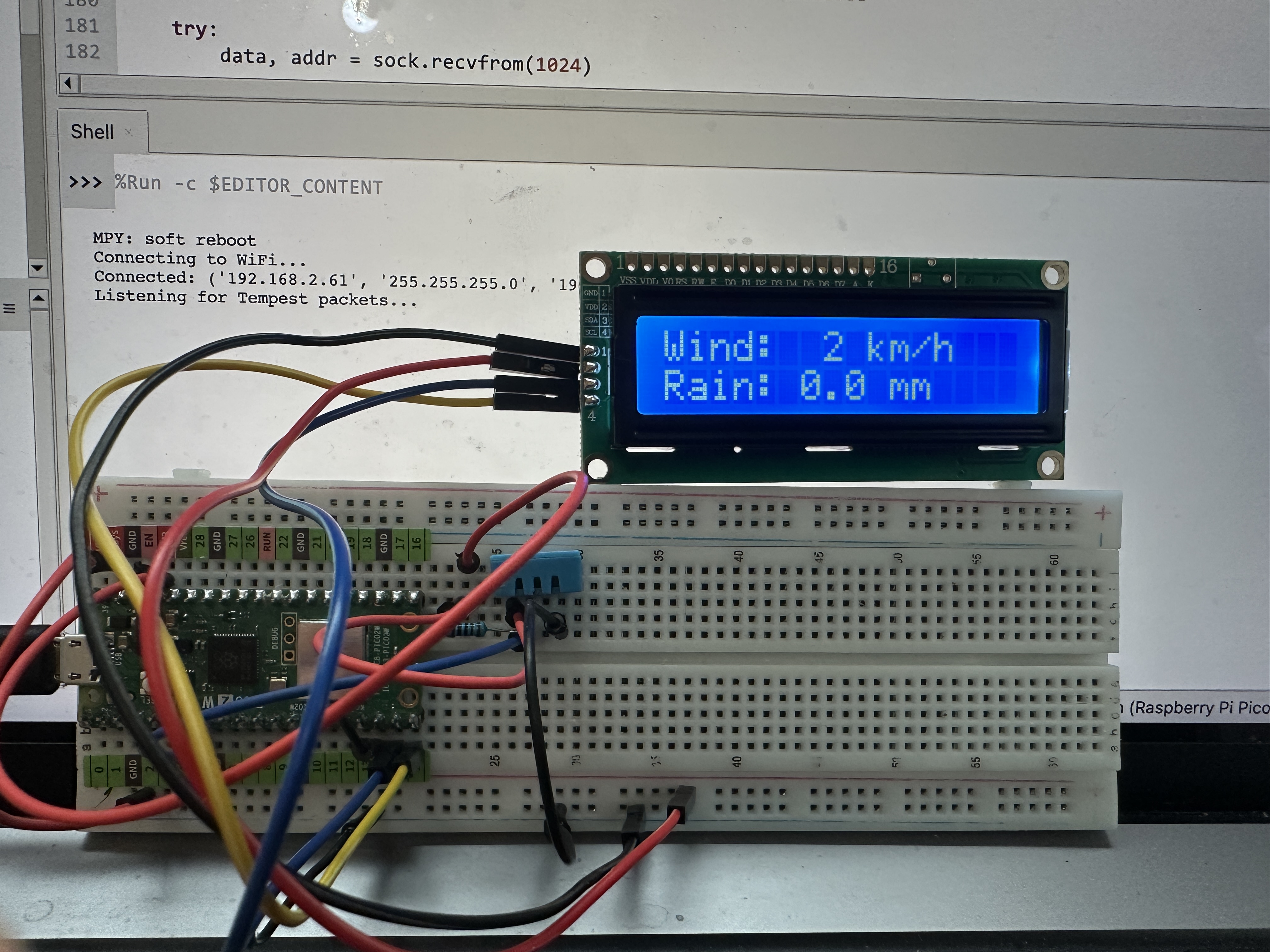
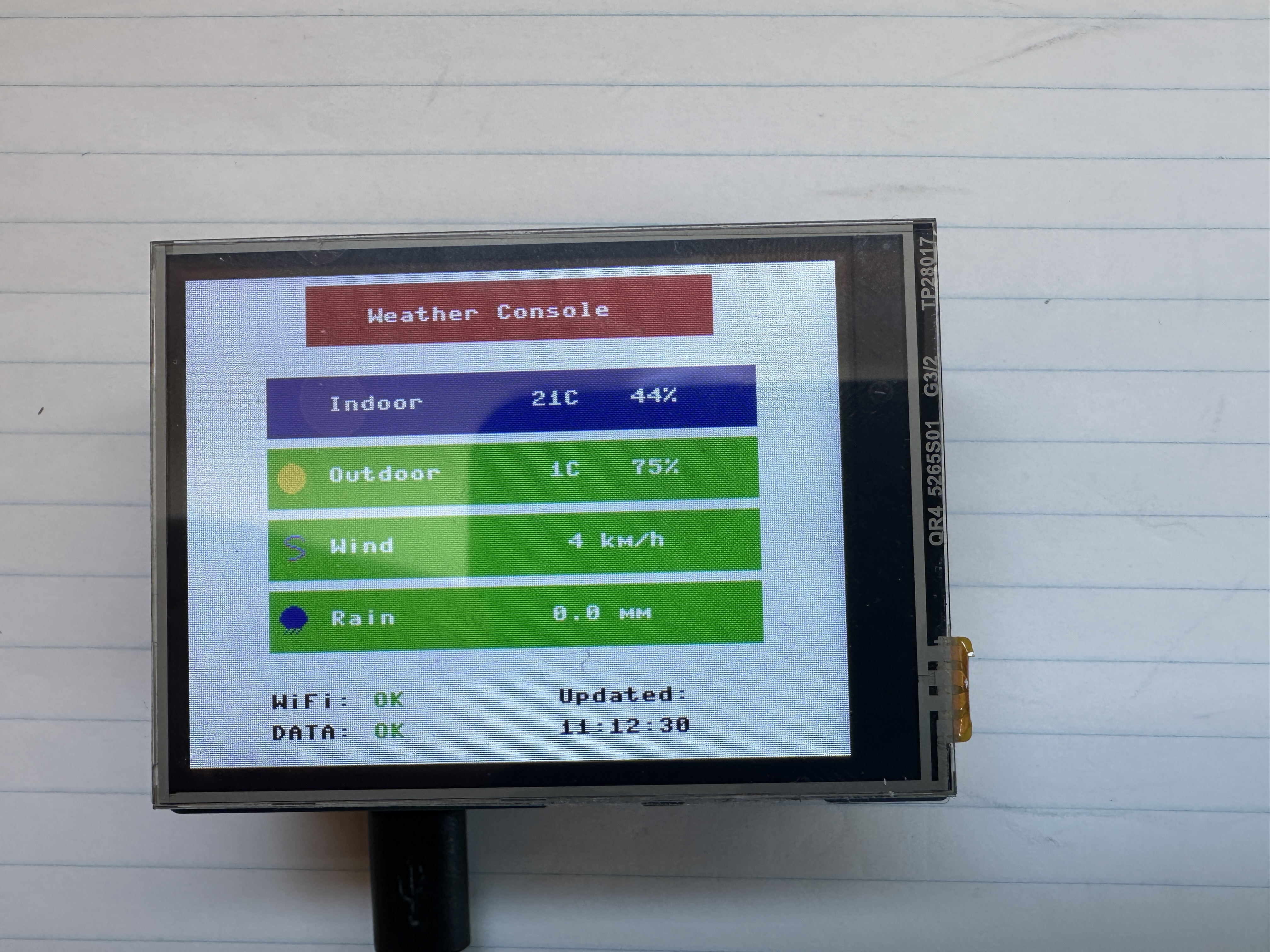
Description
Creates a standalone indoor/outdoor weather console using a Raspberry Pi Pico 2 W and a Waveshare 2.8" LCD Screen. The interface uses a full-screen graphical layout with colour rows and icons to clearly present Indoor, Outdoor, Wind, and Rain data.
Indoor temperature and humidity can be measured locally using an optional DHT22 sensor connected directly to the Pico (recommended to be mounted externally for improved accuracy). Outdoor weather data is received from a Tempest Weather Station using local UDP broadcast packets over WiFi.
The Pico connects to WiFi using credentials stored in a local
config.json file and listens on UDP port 50222
for observation packets transmitted by the Tempest hub.
Temperature, humidity, wind speed, and rainfall values are extracted from the packets and displayed in a clean, non-rotating layout that uses the full 320×240 screen. A footer provides real-time system status including WiFi connectivity, data freshness, and last update time. When sensors are disabled, simulated data is used for UI development and testing.
Time is derived directly from Tempest observation packets, which include
a Unix timestamp (UTC). Local time is calculated using a configurable
timezone offset (tz_offset) stored in config.json,
eliminating the need for NTP synchronization on the Pico.
Features
- Full-screen graphical LCD interface with colour data rows
- Icon-based weather visualization (sun, cloud, rain, wind)
- Indoor temperature and humidity using optional DHT22 sensor
- Outdoor weather data from Tempest Weather Station
- WiFi connection status indicator (colour-coded)
- Data status indicator with timeout detection (DATA:OK / DATA:--)
- Live timestamp showing last received data (Tempest-based)
- Timezone offset configurable via
config.json - WiFi configuration via
config.json - Configurable via flags to enable/disable Tempest and DHT inputs
- Simulated data mode for UI development without hardware
- Wind speed conversion from m/s to km/h
- Non-blocking design for smooth display updates
- Designed to run automatically when saved as
main.py
Hardware
- Raspberry Pi Pico 2 W
- Waveshare Pico-ResTouch-LCD-2.8 (320×240 SPI display)
- DHT22 temperature and humidity sensor (optional, external mount recommended)
- Tempest Weather Station
GPIO Connections
- DHT22 DATA → GPIO14
- DHT22 VCC → 3.3V
- DHT22 GND → GND
- LCD → Integrated SPI interface (handled by driver)
Network Requirements
The Tempest hub must have Local Broadcast enabled in the Tempest mobile app. The Pico must be connected to the same WiFi network as the hub to receive UDP packets.
Configuration
WiFi credentials and timezone settings are stored in a file named
config.json on the Pico filesystem:
{
  "ssid": "YOUR_WIFI",
  "password": "YOUR_PASSWORD",
  "tz_offset": -4,
  "_comment": "tz_offset: -4 = EDT, -5 = EST"
}
Note: JSON does not support comments; the _comment field is optional
and intended for documentation only. The device must be rebooted after updating
this file.
Future Improvements
- Touch interface support
- Signal strength indicator
- Min/max tracking
- Historical graphs
- Additional visual refinements
Architecture
The application is structured into simple functional layers to keep the code modular, maintainable, and easy to extend:
- UI Layer – Handles all LCD rendering using the
framebuf-based driver. Responsible for layout, colours, icons, and on-screen status indicators. - Data Layer – Manages weather data from multiple sources: Tempest UDP packets, optional DHT22 sensor readings, and simulated data when inputs are disabled.
- Network Layer – Handles WiFi connectivity and non-blocking UDP packet reception from the Tempest Weather Station.
- Configuration Layer – Loads runtime settings from
config.json, including WiFi credentials and timezone offset. - State Management – Tracks system status such as last packet time, data freshness, and last update timestamp for display.
This separation allows the UI to remain responsive while data is updated asynchronously, and makes it easy to add new features such as logging, touch interaction, or additional sensors.
Source Code
View Python source: main.py
#######
#
# Project: Indoor / Outdoor Weather Console (Pico 2 W + LCD + Tempest + DHT22)
# Based on Waveshare LCD examples and MicroPython networking/sensor code.
#
# Author: Denis Legault (with help from ChatGPT)
# Date:   2026-03-22
# Python File: main.py
#
# Hardware:
#   - Raspberry Pi Pico 2 W
#   - Waveshare Pico-ResTouch-LCD-2.8 (320x240 SPI display)
#   - DHT22 Temperature and Humidity Sensor (external mount recommended)
#   - Tempest Weather Station (local UDP broadcast)
#
# Description:
#
# Creates a standalone indoor/outdoor weather console using a 2.8" LCD.
# The display uses a full-screen graphical layout with colored rows
# and icons for Indoor, Outdoor, Wind, and Rain data.
#
# Indoor temperature and humidity can be read from a DHT22 sensor
# connected to GPIO14 (optional). The sensor is intended to be mounted
# outside the enclosure for improved accuracy.
#
# Outdoor weather data is received from a Tempest Weather Station
# using local UDP broadcast packets over WiFi.
#
# The system is modular and allows enabling/disabling of:
#   - Tempest UDP data (USE_TEMPEST)
#   - DHT22 sensor input (USE_DHT)
#
# When disabled, simulated data is used for UI development and testing.
#
#
# Time Handling:
#
#   - Tempest "obs_st" packets include a Unix timestamp (epoch) in UTC.
#   - This timestamp is used as the authoritative time source.
#   - Local time is calculated by applying a timezone offset
#     (tz_offset) loaded from config.json.
#   - This avoids the need for NTP synchronization on the Pico.
#
#   Example:
#       local_time = epoch + (tz_offset * 3600)
#
#   Note:
#     - tz_offset = -4 → Eastern Daylight Time (EDT)
#     - tz_offset = -5 → Eastern Standard Time (EST)
#     - DST switching is handled manually by updating config.json.
#
#
# Display Layout:
#
#   -----------------------------------------
#   |        Weather Console (header)       |
#   -----------------------------------------
#   | Indoor   | 21C   40%                  |
#   | Outdoor  |  8C   90%   [icon]         |
#   | Wind     | 12 km/h     [icon]         |
#   | Rain     | 0.2 mm      [icon]         |
#   -----------------------------------------
#   | WiFi:OK       Updated:                |
#   | Data:OK       19:42:08                |
#   -----------------------------------------
#
#
# Features:
#
#   - Full-screen color UI using FrameBuffer graphics
#   - Icon-based weather visualization (sun, cloud, rain, wind)
#   - WiFi connection status indicator (green/red)
#   - Data status indicator with timeout detection (Data:OK / Data:--)
#   - Live timestamp showing last received weather packet
#   - Time derived from Tempest packets (no RTC/NTP required)
#   - Configurable WiFi and timezone via config.json
#   - Simulated data mode for development without sensors or network
#
#
# Network Requirements:
#
#   - Tempest Hub must have Local Broadcast enabled
#   - Pico must connect to the same WiFi network
#   - Tempest broadcasts packets on UDP port 50222
#
#
# Configuration File:
#
#   A file named "config.json" must exist on the Pico filesystem:
#
#   {
#     "ssid": "YOUR_WIFI",
#     "password": "YOUR_PASSWORD",
#     "tz_offset": -4,
#     "_comment": "tz_offset: -4 = EDT, -5 = EST"
#   }
#
#   Notes:
#     - JSON does not support real comments; "_comment" is optional.
#     - Device must be rebooted after updating this file.
#
#
# GPIO Pin Connections:
#
#   DHT22 Sensor (optional)
#     DATA -> GPIO14
#     VCC  -> 3.3V
#     GND  -> GND
#
#   LCD Display
#     Integrated via SPI (handled by lcd_2inch8 driver)
#
#
# Libraries Required:
#
#   - lcd_2inch8.py  (custom Waveshare display driver)
#   - icons.py       (custom icon drawing functions)
#   - mydht.py       (only if USE_DHT = True)
#
#
# Notes:
#
#   - RGB colors use BGR565 conversion for correct display rendering
#   - Wind speed is converted from m/s to km/h
#   - Rainfall is taken directly from Tempest observation data
#   - Display updates once per second
#   - Non-blocking UDP ensures smooth UI performance
#   - Data timeout detection highlights lost Tempest connectivity
#   - Timestamp reflects last valid weather observation received
#   - Designed for clean enclosure wiring and external sensor mounting
#   - Save as main.py to auto-run on boot
#
#######

import time
import math
import json
import network
import socket

from machine import Pin
from lcd_2inch8 import LCD_2inch8
from icons import draw_icon, get_weather_icon, sun_icon, cloud_icon, rain_icon, wind_icon

# --------------------------------------------------
# FLAGS
# --------------------------------------------------

USE_TEMPEST = True
USE_DHT = True
DEBUG_DHT = False
last_dht_print = 0

UDP_PORT = 50222

# --------------------------------------------------
# Last update
# --------------------------------------------------

last_update_time = "--:--:--"
last_packet_ms = time.ticks_ms()
NO_DATA_TIMEOUT = 10000  # 10 seconds
last_update_epoch = None

# --------------------------------------------------
# LOAD CONFIG
# --------------------------------------------------

def load_config():
    try:
        with open("config.json") as f:
            return json.load(f)
    except:
        return {"ssid": "", "password": "", "tz_offset": -5}

config = load_config()
TZ_OFFSET = int(config.get("tz_offset", -5))

# --------------------------------------------------
# Format Time
# --------------------------------------------------

def format_time(epoch):
    if epoch is None:
        return "--:--:--"

    t = time.localtime(epoch + TZ_OFFSET * 3600)
    return "%02d:%02d:%02d" % (t[3], t[4], t[5])

# --------------------------------------------------
# Wifi Status
#---------------------------------------------------

def get_wifi_status():
    if not USE_TEMPEST:
        return "OFF"

    if wlan.isconnected():
        return "OK"

    return "..."

# --------------------------------------------------
# LCD SETUP
# --------------------------------------------------

LCD = LCD_2inch8()
LCD.bl_ctrl(100)

BLACK  = LCD.BLACK
WHITE  = LCD.WHITE
RED    = LCD.RED
GREEN  = LCD.GREEN
BLUE   = LCD.BLUE

def rgb(r, g, b):
    return ((b & 0xF8) << 8) | ((g & 0xFC) << 3) | (r >> 3)

YELLOW = rgb(255, 255, 0)
CYAN   = rgb(0, 255, 255)

# --------------------------------------------------
# STATIC SCREEN
# --------------------------------------------------

def draw_static():
    LCD.fill(WHITE)
    LCD.fill_rect(60, 5, 200, 30, RED)
    LCD.text("Weather Console", 90, 17, WHITE)
    LCD.show_up()


draw_static()


# --------------------------------------------------
# DATA STORE
# --------------------------------------------------

weather = {
    "indoor_temp": 0,
    "indoor_humi": 0,
    "outdoor_temp": 0,
    "outdoor_humi": 0,
    "wind_kmh": 0,
    "rain_mm": 0
}

# Indoor defaults
if not USE_DHT:
    weather["indoor_temp"] = 21
    weather["indoor_humi"] = 40

# Outdoor defaults
if not USE_TEMPEST:
    weather["outdoor_temp"] = 5
    weather["outdoor_humi"] = 80
    weather["wind_kmh"] = 8
    weather["rain_mm"] = 0.2

# --------------------------------------------------
# DHT SETUP
# --------------------------------------------------

if USE_DHT:
    from mydht import DHT22
    dht = DHT22(Pin(14))   # your chosen pin


# --------------------------------------------------
# WIFI + TEMPEST SETUP
# --------------------------------------------------

if USE_TEMPEST:

    wlan = network.WLAN(network.STA_IF)
    wlan.active(True)
    wlan.connect(config["ssid"], config["password"])

    print("Connecting WiFi...")
    while not wlan.isconnected():
        time.sleep(1)

    print("Connected:", wlan.ifconfig())

    sock = socket.socket(socket.AF_INET, socket.SOCK_DGRAM)
    sock.bind(("0.0.0.0", UDP_PORT))
    sock.setblocking(False)

    print("Listening for Tempest...")


# --------------------------------------------------
# ICON COLOR
# --------------------------------------------------

def get_icon_color(icon):
    if icon is sun_icon:
        return YELLOW
    elif icon is cloud_icon:
        return WHITE
    elif icon is rain_icon:
        return BLUE
    elif icon is wind_icon:
        return CYAN
    else:
        return WHITE

# --------------------------------------------------
# UPDATE DISPLAY
# --------------------------------------------------

def update_display():

    LCD.fill_rect(0, 50, 320, 190, WHITE)

    ROW_Y = [50, 85, 120, 155]

    # -----------------------------
    # ICON SELECTION
    # -----------------------------
    outdoor_icon = get_weather_icon(weather)

    # -----------------------------
    # Indoor
    # -----------------------------
    LCD.fill_rect(40, ROW_Y[0], 240, 30, BLUE)

    # label
    LCD.text("Indoor", 70, ROW_Y[0] + 10, WHITE)

    # value
    LCD.text("%2dC   %2d%%" % (
        weather["indoor_temp"],
        weather["indoor_humi"]), 170, ROW_Y[0] + 10, WHITE)

    # -----------------------------
    # Outdoor
    # -----------------------------
    LCD.fill_rect(40, ROW_Y[1], 240, 30, GREEN)

    icon = outdoor_icon
    icon_color = get_icon_color(icon)
    draw_icon(LCD, icon, 45, ROW_Y[1] + 7, icon_color)

    LCD.text("Outdoor", 70, ROW_Y[1] + 10, WHITE)

    LCD.text("%2dC   %2d%%" % (
        weather["outdoor_temp"],
        weather["outdoor_humi"]), 170, ROW_Y[1] + 10, WHITE)

    # -----------------------------
    # Wind
    # -----------------------------
    LCD.fill_rect(40, ROW_Y[2], 240, 30, GREEN)

    # use wind icon directly
    from icons import wind_icon
    draw_icon(LCD, wind_icon, 45, ROW_Y[2] + 7, CYAN)

    LCD.text("Wind", 70, ROW_Y[2] + 10, WHITE)

    LCD.text("%3d km/h" % weather["wind_kmh"], 170, ROW_Y[2] + 10, WHITE)

    # -----------------------------
    # Rain
    # -----------------------------
    LCD.fill_rect(40, ROW_Y[3], 240, 30, GREEN)

    from icons import rain_icon
    draw_icon(LCD, rain_icon, 45, ROW_Y[3] + 7, BLUE)

    LCD.text("Rain", 70, ROW_Y[3] + 10, WHITE)

    LCD.text("%4.1f mm" % weather["rain_mm"], 170, ROW_Y[3] + 10, WHITE)

    # ------------------------------
    # Last updated
    # ------------------------------

    # Clear bottom area
    LCD.fill_rect(0, 200, 320, 30, WHITE)

    # Wifi status
    wifi_status = get_wifi_status()

    LCD.text("WiFi:", 40, 205, BLACK)

    wifi_color = GREEN
    if wifi_status != "OK":
        wifi_color = RED

    LCD.text(wifi_status, 90, 205, wifi_color)

    # Data status
    no_data = time.ticks_diff(time.ticks_ms(), last_packet_ms) > NO_DATA_TIMEOUT

    status_value = "OK"
    status_color = GREEN

    if no_data:
        status_value = "--"
        status_color = RED

    LCD.text("Data:", 40, 220, BLACK)
    LCD.text(status_value, 90, 220, status_color)

    # Draw timestamp
    time_str = format_time(last_update_epoch)
    LCD.text("Updated:", 180, 205, BLACK)
    LCD.text(time_str, 180, 220, BLACK)

    LCD.show_up()

# --------------------------------------------------
# MAIN LOOP
# --------------------------------------------------

last_update = 0

while True:

    t = time.ticks_ms() / 1000

    # -----------------------------
    # Indoor (DHT or dummy)
    # -----------------------------

    if USE_DHT:
        try:
            temp = dht.temperature
            humi = dht.humidity

            if temp is not None and humi is not None:
                weather["indoor_temp"] = int(temp)
                weather["indoor_humi"] = int(humi)

                if DEBUG_DHT and time.ticks_ms() - last_dht_print > 2000:
                    print("DHT OK  Temp:", temp, "Humi:", humi)
                    last_dht_print = time.ticks_ms()
            else:
                if DEBUG_DHT:
                    print("DHT READ NONE")

        except Exception as e:
            if DEBUG_DHT:
                print("DHT ERROR:", e)

    else:
        weather["indoor_temp"] = int(21 + 2 * math.sin(t / 10))
        weather["indoor_humi"] = int(40 + 5 * math.sin(t / 15))

    # -----------------------------
    # Tempest UDP
    # -----------------------------
    if USE_TEMPEST:
        try:
            data, addr = sock.recvfrom(1024)
            packet = json.loads(data)

            last_packet_ms = time.ticks_ms()

            if packet["type"] == "obs_st":
                obs = packet["obs"][0]

                # Get Timestamp
                last_update_epoch = obs[0]

                # Get outdoor weather data
                weather["outdoor_temp"] = int(obs[7])
                weather["outdoor_humi"] = int(obs[8])
                weather["wind_kmh"] = int(obs[2] * 3.6)
                weather["rain_mm"] = obs[12]

        except:
            pass

    else:
        # Dummy outdoor data
        weather["outdoor_temp"] = int(5 + 3 * math.sin(t / 8))
        weather["outdoor_humi"] = int(80 + 10 * math.sin(t / 12))
        weather["wind_kmh"] = int(10 + 5 * math.sin(t / 5))
        weather["rain_mm"] = round(0.2 + 0.1 * math.sin(t / 20), 1)


    # -----------------------------
    # Update display
    # Display updates ≈ 1 time per second (1 Hz)
    # -----------------------------
    if time.ticks_ms() - last_update > 1000:
        update_display()
        last_update = time.ticks_ms()

    # Sleep 50 milliseconds (loop runs 20 times per second)
    time.sleep(0.05)
View Python source: lcd_2inch8.py
#######
#
# File: lcd_2inch8.py
#
# Project: Waveshare 2.8" LCD Driver (ST7789) for Raspberry Pi Pico / Pico 2 W
#
# Adapted and documented by Denis Legault
# Date:    2026-03-21
#
# Description:
#
# Provides a MicroPython driver for the Waveshare Pico-ResTouch-LCD-2.8
# display module using the ST7789 controller. The driver uses the built-in
# FrameBuffer class for fast graphics rendering and supports full 320x240
# landscape mode operation.
#
# The display is driven over SPI and supports 16-bit RGB565 color.
# Drawing operations (text, shapes, icons) are performed in memory and
# then pushed to the display using the show_up() method.
#
# This driver is designed for simple, high-performance graphical UI
# applications such as dashboards, weather displays, and embedded interfaces.
#
#
# Features:
#
#   - 320x240 resolution (landscape orientation)
#   - FrameBuffer-based drawing (fast and flexible)
#   - RGB565 color support
#   - Full-screen buffer rendering
#   - Simple text and shape drawing via FrameBuffer API
#   - Adjustable backlight brightness via PWM
#   - Optional resistive touch support (basic raw coordinates)
#
#
# Display Control:
#
#   - show_up()        → Push frame buffer to screen
#   - fill(color)      → Fill entire screen
#   - fill_rect()      → Draw filled rectangle
#   - text()           → Draw text
#   - pixel()          → Draw individual pixel
#
#
# Color Format:
#
#   Uses RGB565 (16-bit color), but this display expects BGR ordering.
#   Predefined colors are mapped accordingly for correct rendering:
#
#     RED   = 0x07E0
#     GREEN = 0x001F
#     BLUE  = 0xF800
#     WHITE = 0xFFFF
#     BLACK = 0x0000
#
#   Additional colors can be created using a helper rgb(r, g, b) function
#   in application code if needed.
#
#
# Hardware:
#
#   - Raspberry Pi Pico / Pico 2 W
#   - Waveshare Pico-ResTouch-LCD-2.8
#   - ST7789 display controller
#
#
# Pin Configuration:
#
#   LCD_DC   → GPIO8
#   LCD_CS   → GPIO9
#   LCD_SCK  → GPIO10
#   LCD_MOSI → GPIO11
#   LCD_MISO → GPIO12
#   LCD_BL   → GPIO13
#   LCD_RST  → GPIO15
#
#   Touch (optional):
#     TP_CS  → GPIO16
#     TP_IRQ → GPIO17
#
#
# Notes:
#
#   - SPI runs at 60 MHz for fast screen updates
#   - Frame buffer size is ~150 KB (320 × 240 × 2 bytes)
#   - show_up() must be called to refresh the display
#   - Touch input returns raw coordinates and may require calibration
#   - Designed for reuse across multiple projects
#
#######

from machine import Pin, SPI, PWM
import framebuf
import time


# Pin definitions (adjust if needed)
LCD_DC   = 8
LCD_CS   = 9
LCD_SCK  = 10
LCD_MOSI = 11
LCD_MISO = 12
LCD_BL   = 13
LCD_RST  = 15

TP_CS    = 16
TP_IRQ   = 17


class LCD_2inch8(framebuf.FrameBuffer):

    def __init__(self):

        # RGB565 colors
        self.RED   =   0x07E0
        self.GREEN =   0x001f
        self.BLUE  =   0xf800

        self.WHITE =   0xffff
        self.BLACK =   0x0000

        # Landscape mode
        self.width = 320
        self.height = 240

        # Control pins
        self.cs = Pin(LCD_CS, Pin.OUT)
        self.rst = Pin(LCD_RST, Pin.OUT)
        self.dc = Pin(LCD_DC, Pin.OUT)

        # Touch pins (optional)
        self.tp_cs = Pin(TP_CS, Pin.OUT)
        self.irq = Pin(TP_IRQ, Pin.IN)

        self.cs(1)
        self.dc(1)
        self.rst(1)
        self.tp_cs(1)

        # SPI setup
        self.spi = SPI(
            1,
            60_000_000,
            sck=Pin(LCD_SCK),
            mosi=Pin(LCD_MOSI),
            miso=Pin(LCD_MISO)
        )

        # Frame buffer
        self.buffer = bytearray(self.height * self.width * 2)
        super().__init__(self.buffer, self.width, self.height, framebuf.RGB565)

        self.init_display()


    # ----------------------------------------------------------
    # Low-level write functions
    # ----------------------------------------------------------

    def write_cmd(self, cmd):
        self.cs(1)
        self.dc(0)
        self.cs(0)
        self.spi.write(bytearray([cmd]))
        self.cs(1)

    def write_data(self, data):
        self.cs(1)
        self.dc(1)
        self.cs(0)
        self.spi.write(bytearray([data]))
        self.cs(1)


    # ----------------------------------------------------------
    # Initialize display
    # ----------------------------------------------------------

    def init_display(self):

        self.rst(1)
        time.sleep_ms(5)
        self.rst(0)
        time.sleep_ms(10)
        self.rst(1)
        time.sleep_ms(5)

        self.write_cmd(0x11)  # Sleep out
        time.sleep_ms(100)

        self.write_cmd(0x36)
        self.write_data(0x60)  # Landscape

        self.write_cmd(0x3A)
        self.write_data(0x55)  # 16-bit color

        self.write_cmd(0xB2)
        self.write_data(0x0C)
        self.write_data(0x0C)
        self.write_data(0x00)
        self.write_data(0x33)
        self.write_data(0x33)

        self.write_cmd(0xB7)
        self.write_data(0x35)

        self.write_cmd(0xBB)
        self.write_data(0x28)

        self.write_cmd(0xC0)
        self.write_data(0x3C)

        self.write_cmd(0xC2)
        self.write_data(0x01)

        self.write_cmd(0xC3)
        self.write_data(0x0B)

        self.write_cmd(0xC4)
        self.write_data(0x20)

        self.write_cmd(0xC6)
        self.write_data(0x0F)

        self.write_cmd(0xD0)
        self.write_data(0xA4)
        self.write_data(0xA1)

        self.write_cmd(0xE0)
        for d in [
            0xD0,0x01,0x08,0x0F,0x11,0x2A,0x36,0x55,
            0x44,0x3A,0x0B,0x06,0x11,0x20
        ]:
            self.write_data(d)

        self.write_cmd(0xE1)
        for d in [
            0xD0,0x02,0x07,0x0A,0x0B,0x18,0x34,0x43,
            0x4A,0x2B,0x1B,0x1C,0x22,0x1F
        ]:
            self.write_data(d)

        self.write_cmd(0x55)
        self.write_data(0xB0)

        self.write_cmd(0x29)  # Display ON


    # ----------------------------------------------------------
    # Update display
    # ----------------------------------------------------------

    def show_up(self):

        self.write_cmd(0x2A)
        self.write_data(0x00)
        self.write_data(0x00)
        self.write_data(0x01)
        self.write_data(0x3F)

        self.write_cmd(0x2B)
        self.write_data(0x00)
        self.write_data(0x00)
        self.write_data(0x00)
        self.write_data(0xEF)

        self.write_cmd(0x2C)

        self.cs(1)
        self.dc(1)
        self.cs(0)
        self.spi.write(self.buffer)
        self.cs(1)


    # ----------------------------------------------------------
    # Backlight control
    # ----------------------------------------------------------

    def bl_ctrl(self, duty):
        pwm = PWM(Pin(LCD_BL))
        pwm.freq(1000)

        if duty >= 100:
            pwm.duty_u16(65535)
        else:
            pwm.duty_u16(int(65535 * duty / 100))


    # ----------------------------------------------------------
    # Touch read (optional)
    # ----------------------------------------------------------

    def touch_get(self):

        if self.irq() == 0:

            self.spi = SPI(1, 5_000_000,
                           sck=Pin(LCD_SCK),
                           mosi=Pin(LCD_MOSI),
                           miso=Pin(LCD_MISO))

            self.tp_cs(0)

            x = 0
            y = 0

            for _ in range(3):

                self.spi.write(bytearray([0xD0]))
                rx = self.spi.read(2)
                x += ((rx[0] << 8) + rx[1]) >> 3

                self.spi.write(bytearray([0x90]))
                ry = self.spi.read(2)
                y += ((ry[0] << 8) + ry[1]) >> 3

            self.tp_cs(1)

            self.spi = SPI(1, 60_000_000,
                           sck=Pin(LCD_SCK),
                           mosi=Pin(LCD_MOSI),
                           miso=Pin(LCD_MISO))

            return [x // 3, y // 3]

        return None
View Python source: icons.py
#######
#
# Icon Definitions and Rendering Utilities
#
# Description:
#
# Provides simple 16x16 monochrome bitmap icons and helper functions
# for rendering them on the LCD using the FrameBuffer pixel interface.
#
# Icons are defined as lists of 16 integers, where each integer represents
# one row of pixels. Each bit in the integer corresponds to a pixel:
#
#   - 1 = pixel ON (drawn using specified color)
#   - 0 = pixel OFF (transparent / not drawn)
#
# Bitmaps are drawn left-to-right using the most significant bit (MSB).
#
#
# Icon Format:
#
#   - Size: 16 x 16 pixels
#   - Data: list of 16 rows (16-bit values)
#   - Rendering: binary mask using bitwise operations
#
#
# Available Icons:
#
#   - sun_icon   → clear / sunny conditions
#   - cloud_icon → cloudy / high humidity
#   - rain_icon  → rain detected
#   - wind_icon  → strong wind conditions
#
#
# Rendering Function:
#
#   draw_icon(lcd, icon, x, y, color)
#
#     lcd   → LCD FrameBuffer object
#     icon  → icon bitmap (16x16 list)
#     x, y  → top-left position on screen
#     color → RGB565 color
#
#   Draws only "ON" pixels, leaving background untouched.
#
#
# Icon Selection Logic:
#
#   get_weather_icon(weather)
#
#   Selects an icon based on current weather conditions:
#
#     - rain_icon  → if rain_mm > 0
#     - wind_icon  → if wind_kmh > 25
#     - cloud_icon → if humidity > 85%
#     - sun_icon   → default (clear conditions)
#
#   Priority order ensures rain and wind override general conditions.
#
#
# Notes:
#
#   - Icons are intentionally simple for performance and readability
#   - Designed for fast rendering on microcontrollers
#   - Can be easily extended with additional icons (e.g., snow, storm)
#   - Colors are applied at draw time, not stored in the bitmap
#
#######

# --------------------------------------------------
# ICON DATA
# --------------------------------------------------

sun_icon = [
    0b0000011110000000,
    0b0001111111100000,
    0b0011111111110000,
    0b0111111111111000,
    0b0111111111111000,
    0b1111111111111100,
    0b1111111111111100,
    0b1111111111111100,
    0b1111111111111100,
    0b1111111111111100,
    0b0111111111111000,
    0b0111111111111000,
    0b0011111111110000,
    0b0001111111100000,
    0b0000011110000000,
    0b0000000000000000
]

cloud_icon = [
    0b0000000000000000,
    0b0000011110000000,
    0b0001111111100000,
    0b0011111111110000,
    0b0111111111111000,
    0b0111111111111000,
    0b1111111111111100,
    0b1111111111111100,
    0b1111111111111100,
    0b0111111111111000,
    0b0011111111110000,
    0b0001111111100000,
    0b0000000000000000,
    0b0000000000000000,
    0b0000000000000000,
    0b0000000000000000
]

rain_icon = [
    0b0000011110000000,
    0b0001111111100000,
    0b0011111111110000,
    0b0111111111111000,
    0b0111111111111000,
    0b1111111111111100,
    0b1111111111111100,
    0b1111111111111100,
    0b0111111111111000,
    0b0011111111110000,
    0b0001111111100000,
    0b0000100100100000,
    0b0001001001000000,
    0b0010010010000000,
    0b0000000000000000,
    0b0000000000000000
]

wind_icon = [
    0b0000000000000000,
    0b0000001111100000,
    0b0000110000010000,
    0b0001000000001000,
    0b0001000000000000,
    0b0000110000000000,
    0b0000001110000000,
    0b0000000001100000,
    0b0000000000011000,
    0b0000000000001000,
    0b0000000000011000,
    0b0000000001100000,
    0b0000011110000000,
    0b0000000000000000,
    0b0000000000000000,
    0b0000000000000000
]


# --------------------------------------------------
# DRAW FUNCTION
# --------------------------------------------------

def draw_icon(lcd, icon, x, y, color):
    for row, bits in enumerate(icon):
        for col in range(16):
            if bits & (1 << (15 - col)):
                lcd.pixel(x + col, y + row, color)


# --------------------------------------------------
# ICON LOGIC
# --------------------------------------------------

def get_weather_icon(weather):

    if weather["rain_mm"] > 0:
        return rain_icon

    elif weather["wind_kmh"] > 25:
        return wind_icon

    elif weather["outdoor_humi"] > 85:
        return cloud_icon

    else:
        return sun_icon
View Python source: mydht.py
#######
#
# Module: DHT11 / DHT22 Temperature and Humidity Sensor Driver
# Based on open-source MicroPython DHT sensor implementations.
#
# Adapted and documented by Denis Legault
# Date: 2026-03-17
# Python File: mydht.py
# Hardware: Raspberry Pi Pico / Pico 2 W,
#           DHT11 or DHT22 Temperature and Humidity Sensor
#
# Description:
# Provides a MicroPython driver for reading temperature and humidity
# from DHT11 and DHT22 digital sensors. The driver communicates with
# the sensor using a single GPIO pin and measures precise pulse timing
# to decode the transmitted data.
#
# The sensor sends 40 bits of data containing humidity, temperature,
# and a checksum. This module captures pulse timings, converts them
# into binary values, and validates the checksum before returning
# sensor readings.
#
# Features:
# - Supports both DHT11 and DHT22 sensors
# - Reads temperature and humidity values
# - Automatic timing control between measurements
# - Pulse timing capture for decoding sensor data
# - Checksum validation for data integrity
# - Automatic retry on read failure for improved reliability
#
# Notes:
# - DHT11 minimum interval ~1 second
# - DHT22 minimum interval ~2 seconds
# - Uses microsecond timing to decode the digital signal
# - Returns last valid reading if a read fails
#
# GPIO Connection:
# DATA -> Pico GPIO pin (example GPIO16)
# VCC  -> 3.3V
# GND  -> GND
#
# A 10kΩ pull-up resistor between DATA and VCC is recommended.
#
# Usage example:
#   from mydht import DHT11
#   dht = DHT11(Pin(5))
#
#   from mydht import DHT22
#   dht = DHT22(Pin(5))
#
#######

import array
import micropython
import utime
from machine import Pin
from micropython import const


# --------------------------------------------------------------
# Custom Exceptions
# --------------------------------------------------------------

class InvalidChecksum(Exception):
    pass


class InvalidPulseCount(Exception):
    pass


# --------------------------------------------------------------
# Timing and Protocol Constants
# --------------------------------------------------------------

MAX_UNCHANGED = const(100)          # Timeout for pulse capture loop
MIN_INTERVAL_US_DHT11 = const(1000000)   # 1 second minimum interval
MIN_INTERVAL_US_DHT22 = const(2000000)   # 2 seconds minimum interval

HIGH_LEVEL = const(50)              # Threshold to distinguish 0 vs 1
EXPECTED_PULSES = const(84)         # Expected number of transitions


# --------------------------------------------------------------
# Base Class (Shared Logic)
# --------------------------------------------------------------

class DHTBase:
    """
    Base class for DHT sensors (shared pulse timing logic).
    """

    def __init__(self, pin, min_interval):
        # GPIO pin used for sensor communication
        self._pin = pin

        # Last successful measurement timestamp
        self._last_measure = utime.ticks_us()

        # Cached values (None until first valid reading)
        self._temperature = None
        self._humidity = None

        # Minimum interval between reads (sensor-specific)
        self._min_interval = min_interval


    def measure(self):
        """
        Initiates a measurement cycle and updates sensor values.
        Includes automatic retry for improved reliability.
        """

        current_ticks = utime.ticks_us()

        # Respect minimum interval between reads
        if utime.ticks_diff(current_ticks, self._last_measure) < self._min_interval and (
            self._temperature is not None or self._humidity is not None
        ):
            return

        # Try reading sensor (with one retry on failure)
        for _ in range(2):

            try:
                # Send start signal to sensor
                self._send_init_signal()

                # Capture pulse timings
                pulses = self._capture_pulses()

                # Convert pulses into data bytes
                buffer = self._convert_pulses_to_buffer(pulses)

                # Validate checksum
                self._verify_checksum(buffer)

                # Decode sensor-specific values
                self._decode(buffer)

                # Update timestamp only on success
                self._last_measure = utime.ticks_us()

                return

            except (InvalidChecksum, InvalidPulseCount):
                # Retry once if read fails
                continue


    @property
    def humidity(self):
        """Return humidity value (%)"""
        self.measure()
        return self._humidity


    @property
    def temperature(self):
        """Return temperature value (°C)"""
        self.measure()
        return self._temperature


    # ----------------------------------------------------------
    # Shared Low-Level Functions
    # ----------------------------------------------------------

    def _send_init_signal(self):
        """
        Sends the start signal required by the DHT protocol.
        """

        self._pin.init(Pin.OUT, Pin.PULL_DOWN)

        # Pull line HIGH briefly
        self._pin.value(1)
        utime.sleep_ms(50)

        # Pull line LOW to initiate communication
        self._pin.value(0)
        utime.sleep_ms(18)


    @micropython.native
    def _capture_pulses(self):
        """
        Captures pulse timing transitions sent by the sensor.
        Timing accuracy is critical for correct decoding.
        """

        pin = self._pin
        pin.init(Pin.IN, Pin.PULL_UP)

        val = 1
        idx = 0
        transitions = bytearray(EXPECTED_PULSES)

        unchanged = 0
        timestamp = utime.ticks_us()

        while unchanged < MAX_UNCHANGED:

            if val != pin.value():

                if idx >= EXPECTED_PULSES:
                    raise InvalidPulseCount(
                        "Got more than {} pulses".format(EXPECTED_PULSES)
                    )

                now = utime.ticks_us()

                transitions[idx] = now - timestamp
                timestamp = now
                idx += 1

                val = 1 - val
                unchanged = 0

            else:
                unchanged += 1

        # Return pin to safe state
        pin.init(Pin.OUT, Pin.PULL_DOWN)

        if idx != EXPECTED_PULSES:
            raise InvalidPulseCount(
                "Expected {} but got {} pulses".format(EXPECTED_PULSES, idx)
            )

        # Skip first 4 transitions (sensor response preamble)
        return transitions[4:]


    def _convert_pulses_to_buffer(self, pulses):
        """
        Convert captured pulse timings into 5 bytes of data.
        """

        binary = 0

        # Convert pulse widths to bits
        for idx in range(0, len(pulses), 2):
            binary = binary << 1 | int(pulses[idx] > HIGH_LEVEL)

        buffer = array.array("B")

        # Split 40-bit value into 5 bytes
        for shift in range(4, -1, -1):
            buffer.append(binary >> shift * 8 & 0xFF)

        return buffer


    def _verify_checksum(self, buffer):
        """
        Validate sensor data using checksum.
        """

        checksum = 0

        for buf in buffer[0:4]:
            checksum += buf

        if checksum & 0xFF != buffer[4]:
            raise InvalidChecksum()


    def _decode(self, buffer):
        """
        Implemented by subclasses (DHT11 / DHT22).
        """
        raise NotImplementedError


# --------------------------------------------------------------
# DHT11 Implementation
# --------------------------------------------------------------

class DHT11(DHTBase):
    """
    Driver for DHT11 sensor.
    """

    def __init__(self, pin):
        super().__init__(pin, MIN_INTERVAL_US_DHT11)


    def _decode(self, buffer):
        """
        Decode DHT11 data format (integer values).
        """

        self._humidity = buffer[0] + buffer[1] / 10
        self._temperature = buffer[2] + buffer[3] / 10


# --------------------------------------------------------------
# DHT22 Implementation
# --------------------------------------------------------------

class DHT22(DHTBase):
    """
    Driver for DHT22 sensor.
    """

    def __init__(self, pin):
        super().__init__(pin, MIN_INTERVAL_US_DHT22)


    def _decode(self, buffer):
        """
        Decode DHT22 data format (16-bit values with decimals).
        """

        humidity_raw = (buffer[0] << 8) | buffer[1]
        temperature_raw = (buffer[2] << 8) | buffer[3]

        # Convert humidity (scale by 10)
        self._humidity = humidity_raw / 10

        # Handle negative temperature values
        if temperature_raw & 0x8000:
            temperature_raw = -(temperature_raw & 0x7FFF)

        self._temperature = temperature_raw / 10
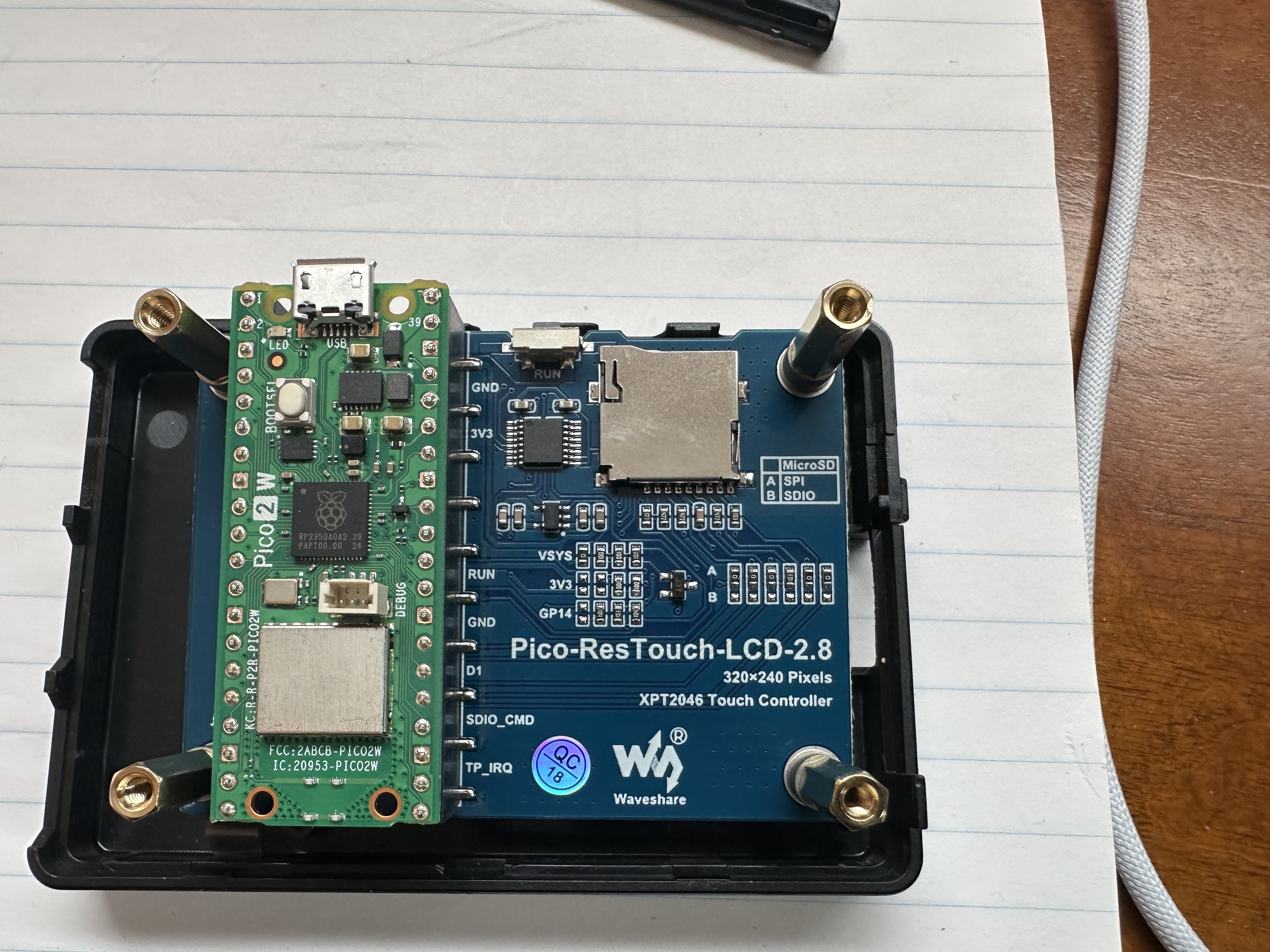
The Raspberry Pi Pico 2 W (green board) plugs directly into the back of the Wave share Pico-ResTouch-LCD-2.8 module, forming a compact all-in-one unit. The LCD board provides the SPI display, touch controller, backlight control, and an onboard microSD card slot for storage.
Waveshare provides example libraries and drivers in both MicroPython and C/C++ to interface with the display, touch input, and SD card. These libraries handle low-level communication (SPI, control pins, and display initialization), allowing the application code to focus on rendering graphics and processing data.
The microSD card slot can be used to store configuration files, assets (such as
images or fonts), or logged weather data, making it useful for future expansion
of the project. In this implementation, the display is driven using a custom
lcd_2inch8.py driver based on Waveshare examples, along with standard
MicroPython libraries such as framebuf, network,
socket, and json.
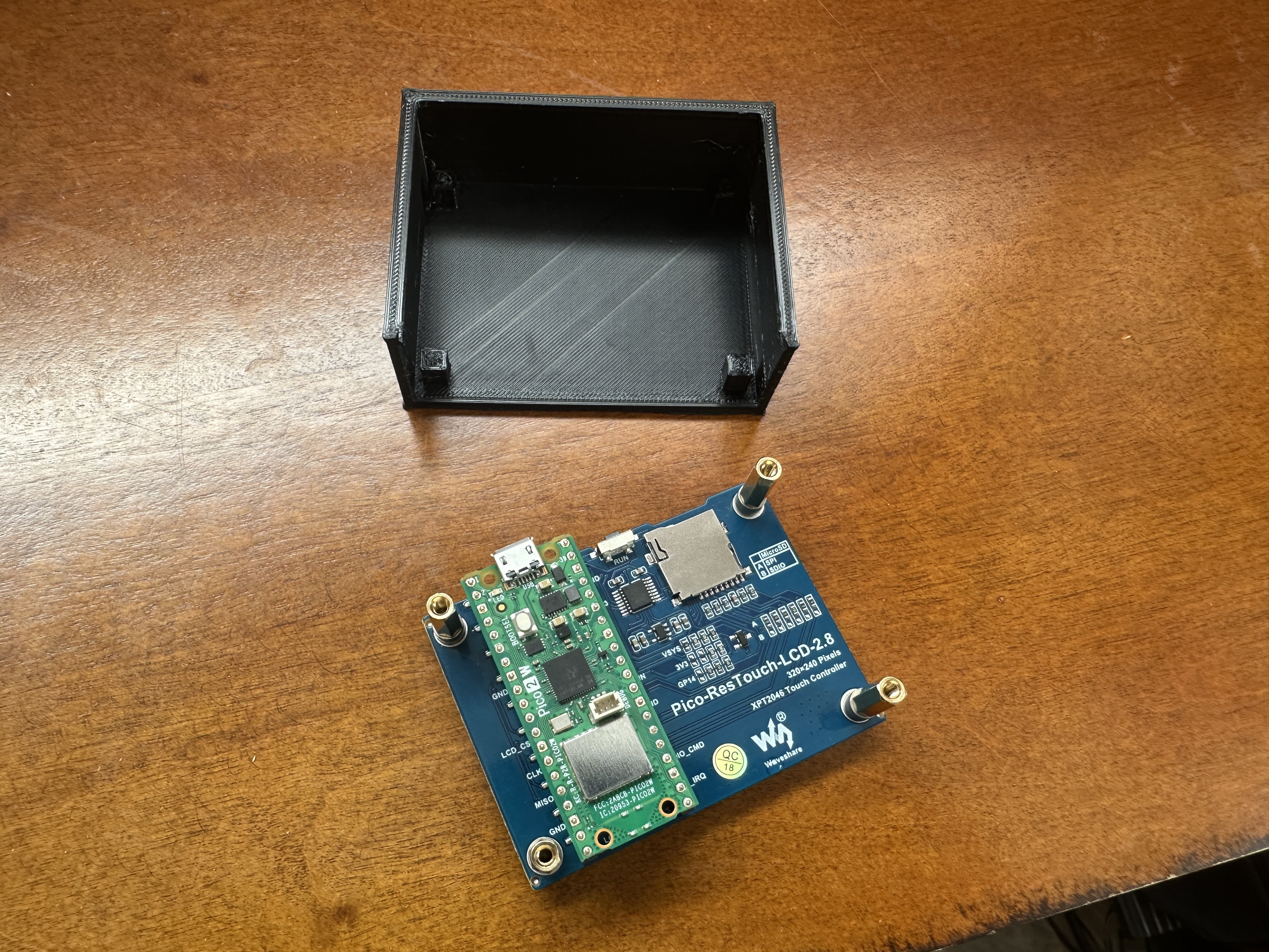
Used a 3D printer to create a wall-mount case for the display. The design was generated with assistance from ChatGPT using measurements from the product page.
The case includes a bottom opening to allow access to the USB connector, reset button, microSD card slot, and wiring for the external DHT22 sensor.
Mounting standoffs are positioned to align with the board holes, and spacing offsets were adjusted to avoid contact with onboard components (including buttons and connectors). The display is held securely while allowing easy removal if needed.
Open areas and venting were intentionally included to improve airflow and reduce heat buildup, helping ensure more accurate temperature readings from the external sensor.
Designed for simple wall mounting with clean cable routing and minimal visible wiring.
Printed in PLA using standard settings (0.2 mm layer height, 15% infill).
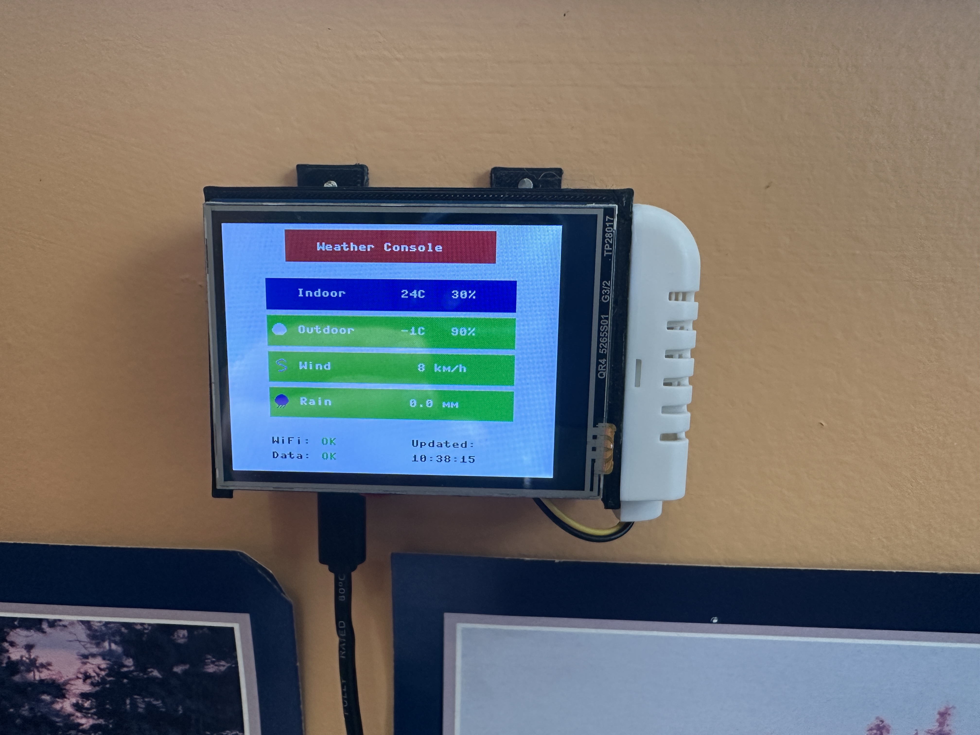
Wall-mounted installation of the completed weather console. The display unit is secured in the custom 3D-printed case, with a clean cable exit at the bottom for power.
The DHT22 temperature and humidity sensor is mounted externally on the right side in its own protective white enclosure, allowing for improved airflow and more accurate indoor readings compared to placing it inside the main case.
This setup provides a compact, clean installation while keeping the sensor properly positioned for reliable measurements.
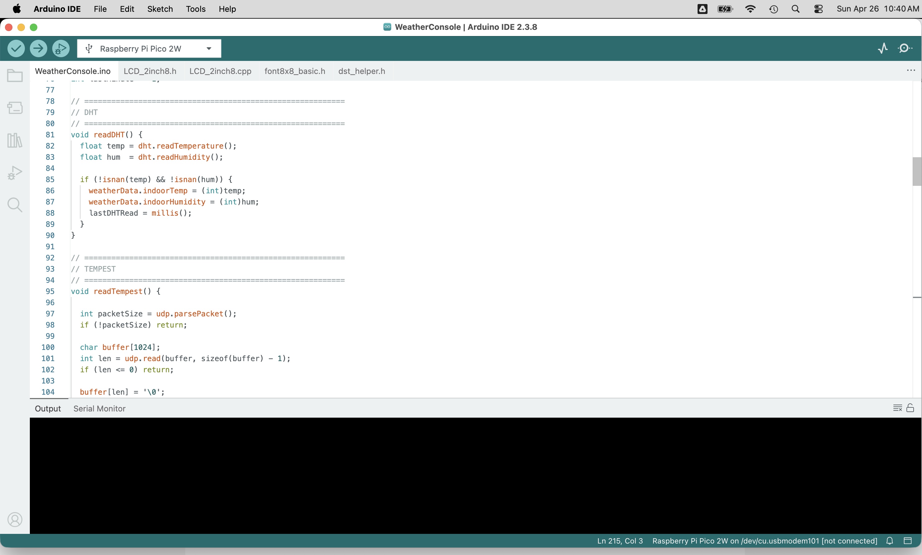
Arduino IDE (C/C++)
The Arduino IDE provides a simple way to program the Raspberry Pi Pico using C and C++ via the Arduino framework.
When you click Upload, the code is compiled into native machine code and flashed directly to the Pico’s memory, where it runs at full speed on the microcontroller.
Unlike MicroPython in Arduino IDE, C/C++ programs are compiled ahead of time, giving you precise control over execution timing, lower latency, and more efficient use of memory.
This makes the Arduino environment ideal for performance-critical tasks such as real-time control, accurate timing loops, motor control, and handling high-frequency I/O.
- Faster execution (compiled vs interpreted)
- Deterministic timing for real-time applications
- Lower memory overhead
- Access to low-level hardware features
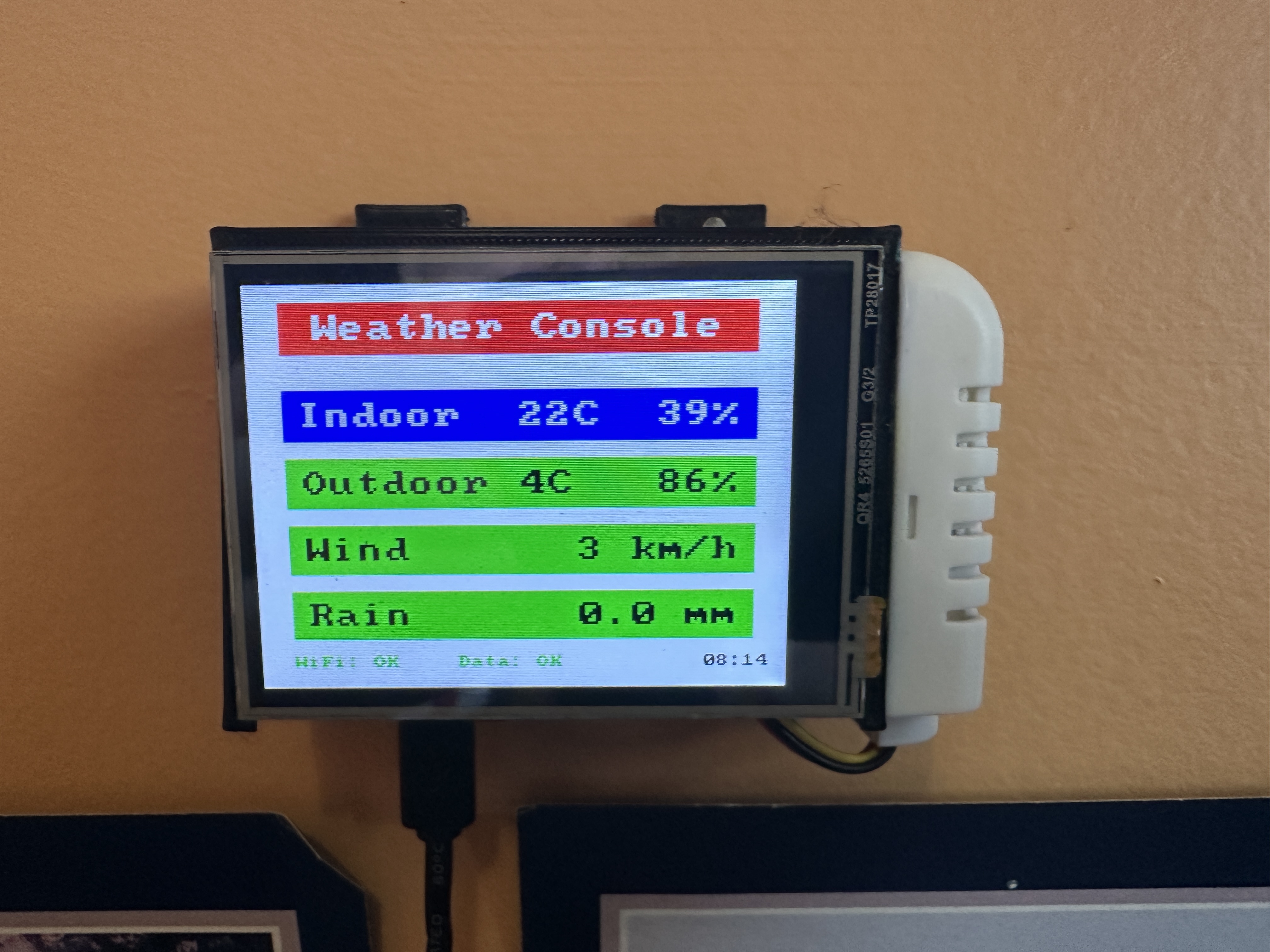
Description
Ported Weather Console from Thonny/MicroPython to the Arduino IDE using C++. This version runs as compiled native code on the Raspberry Pi Pico 2 W, providing improved performance, more precise timing, and better control over hardware resources.
Creates a standalone indoor/outdoor weather console using a Waveshare 2.8" LCD screen with a full-screen graphical layout. Colour-coded rows and icons clearly present Indoor, Outdoor, Wind, and Rain data.
Indoor temperature and humidity can be measured locally using an optional DHT22 sensor (recommended to be mounted externally for improved accuracy). Outdoor weather data is received from a Tempest Weather Station using local UDP broadcast packets over WiFi.
The Pico connects to WiFi using credentials defined in the source code and listens on UDP port 50222
for observation packets transmitted by the Tempest hub.
Data is displayed in a clean, non-rotating 320×240 layout with a footer showing real-time system status including WiFi connectivity, data freshness, and last update time.
Why C++ / Arduino?
The move to C++ enables faster screen rendering, smoother updates, and precise timing control—critical for responsive UI and sensor handling. This becomes especially important as the project evolves to support multiple screens, touch input, and more complex user interaction.
Running as compiled code eliminates interpreter overhead, allowing tighter control of update loops, more consistent frame timing, and better scalability as features are added (such as menus, screen navigation, and touch-driven input).
Features
- Full-screen graphical LCD interface with colour data rows
- Indoor temperature and humidity using optional DHT22 sensor
- Outdoor weather data from Tempest Weather Station (UDP broadcast)
- WiFi connection status indicator (colour-coded)
- Data status indicator with timeout detection (DATA:OK / DATA:--)
- Live timestamp showing last received data (Tempest-based)
- WiFi credentials configured in code
- Wind speed conversion from m/s to km/h
- Non-blocking design for smooth and consistent updates
- Compiled C++ code for improved performance and timing accuracy
- Designed as a foundation for multi-screen and touch-enabled interface
Hardware
- Raspberry Pi Pico 2 W
- Waveshare Pico-ResTouch-LCD-2.8 (320×240 SPI display with touch)
- DHT22 temperature and humidity sensor (optional)
- Tempest Weather Station
GPIO Connections
- DHT22 DATA → GPIO14
- DHT22 VCC → 3.3V
- DHT22 GND → GND
- LCD → Integrated SPI interface (handled by driver)
Network Requirements
The Tempest hub must have Local Broadcast enabled in the Tempest mobile app. The Pico must be connected to the same WiFi network as the hub to receive UDP packets.
Source Code
WeatherConsole.ino
LCD_2inch8.h
LCD_2inch8.cpp
dst_helper.h
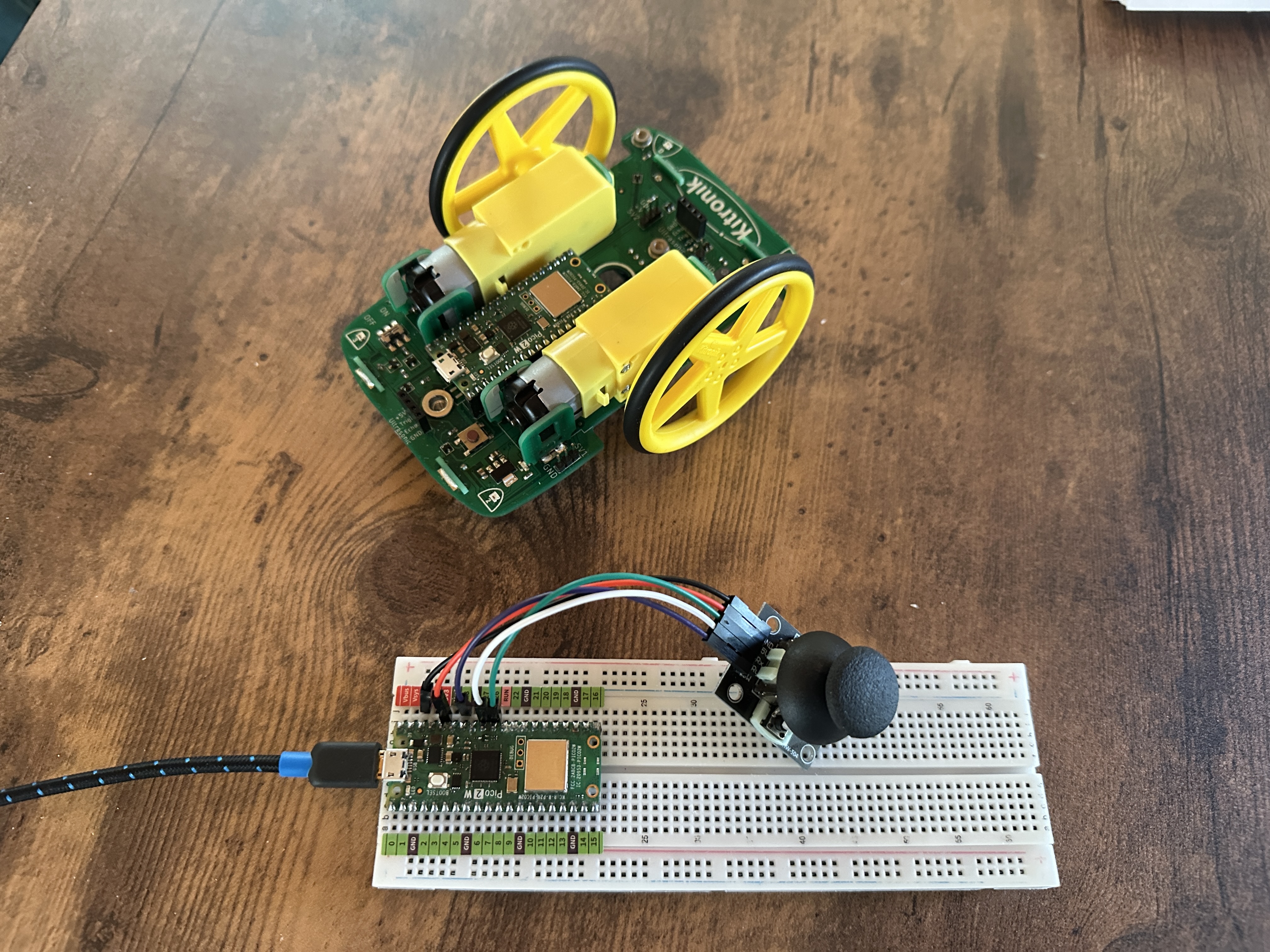
Kitronik Automated Robotic Platform (Pico 2 W)
This project uses the Kitronik Automated Robotic Platform with two Raspberry Pi Pico 2 W boards to create a wireless remote-controlled vehicle. One Pico acts as the controller, while the other runs on the car, handling motor control and onboard features.
Communication between the controller and car is handled over WiFi using lightweight UDP packets, allowing fast, low-latency control without the overhead of more complex protocols.
System Architecture
- Controller Pico 2 W
- Reads joystick input (X/Y) and button states
- Connects to the car’s WiFi access point
- Sends control data over UDP
- Acts as the user interface for driving the vehicle
- Car Pico 2 W
- Creates a dedicated WiFi access point (AP mode)
- Receives UDP packets from the controller
- Controls motors (speed and direction)
- Handles onboard features (LEDs, status indicators)
- Implements failsafe stop if communication is lost
WiFi Communication
The car Pico operates in Access Point (AP) mode, creating its own private WiFi network. The controller Pico connects directly to this network, eliminating the need for an external router and enabling fully self-contained operation.
The controller transmits small UDP packets containing joystick position and button data. These packets are received by the car in real time and used to update motor control and system state.
UDP is used because it is lightweight and fast—ideal for responsive control where occasional packet loss is acceptable. Continuous packet transmission ensures smooth and responsive driving.
Failsafe Behavior
To ensure safe operation, the car includes a failsafe mechanism. If no control packets are received within a short timeout period (typically a few hundred milliseconds), the motors are stopped automatically. This prevents unintended movement if the connection is interrupted.
Key Advantages
- Direct device-to-device WiFi connection (no router required)
- Low-latency control using UDP
- Fully self-contained wireless system
- Modular design (separate controller and vehicle logic)
- Scalable for additional features (telemetry, sensors, UI)
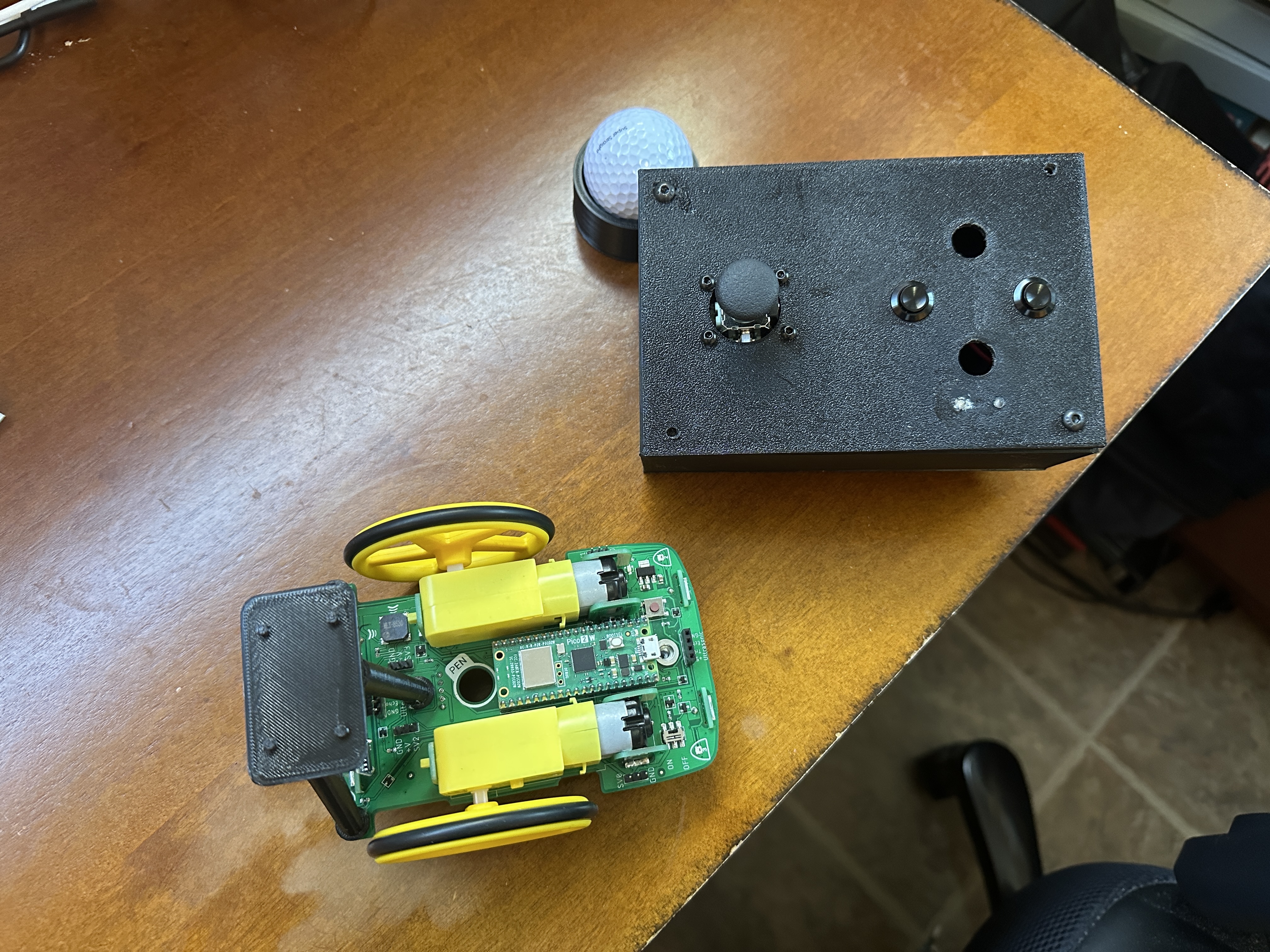
Joystick, buttons and LEDs in 3D printed case.
Battery pack (3 AA) provides power to the controller.
Car/buggy has battery pack (4 AA) underneath.
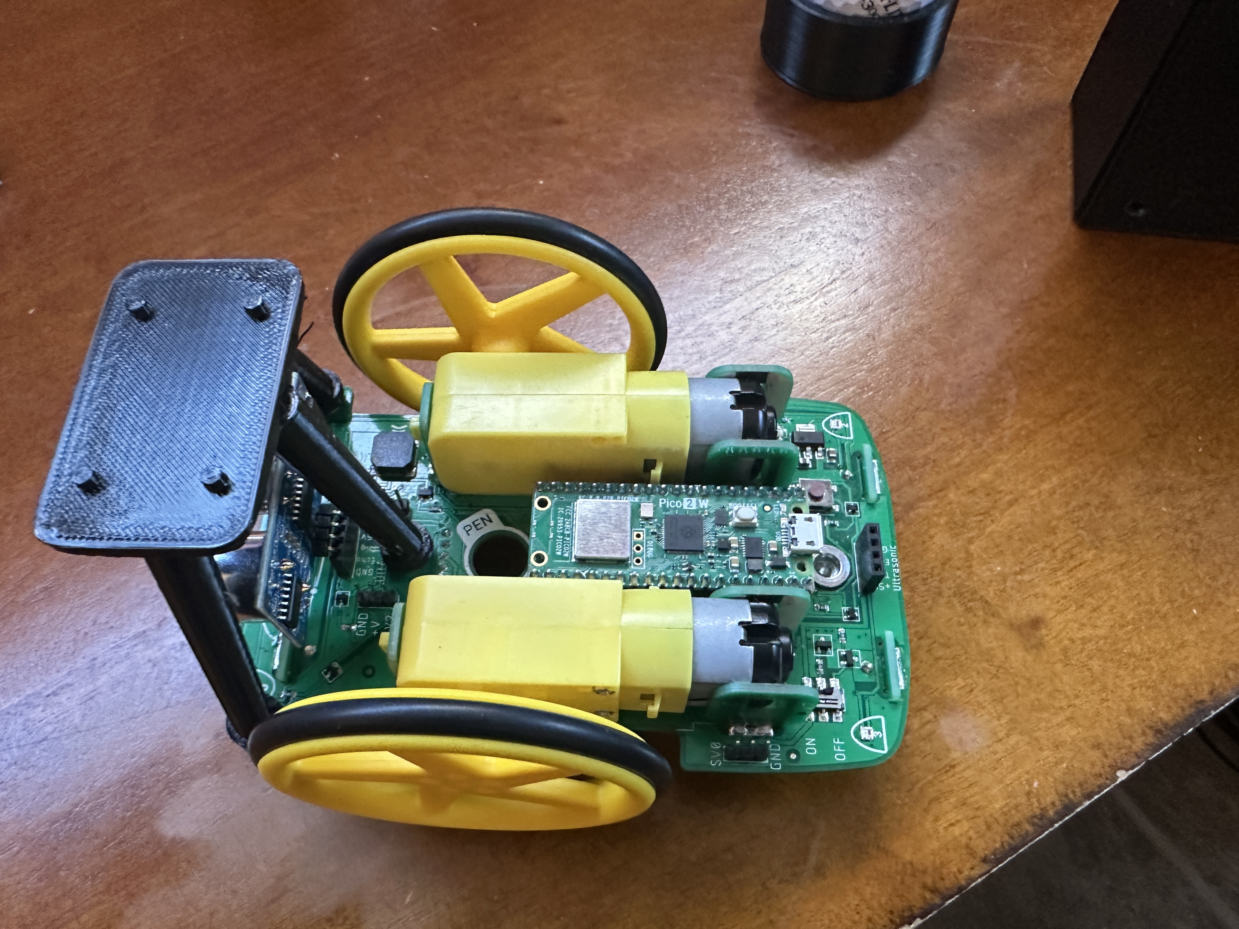
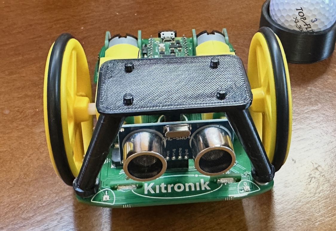
Ultrasonic sensor used to measure distances and avoid obstacles. Sensor on the back of car available.
Connectors available on board for stepper motors.
Infrared Line Tracking sensor underneath car.
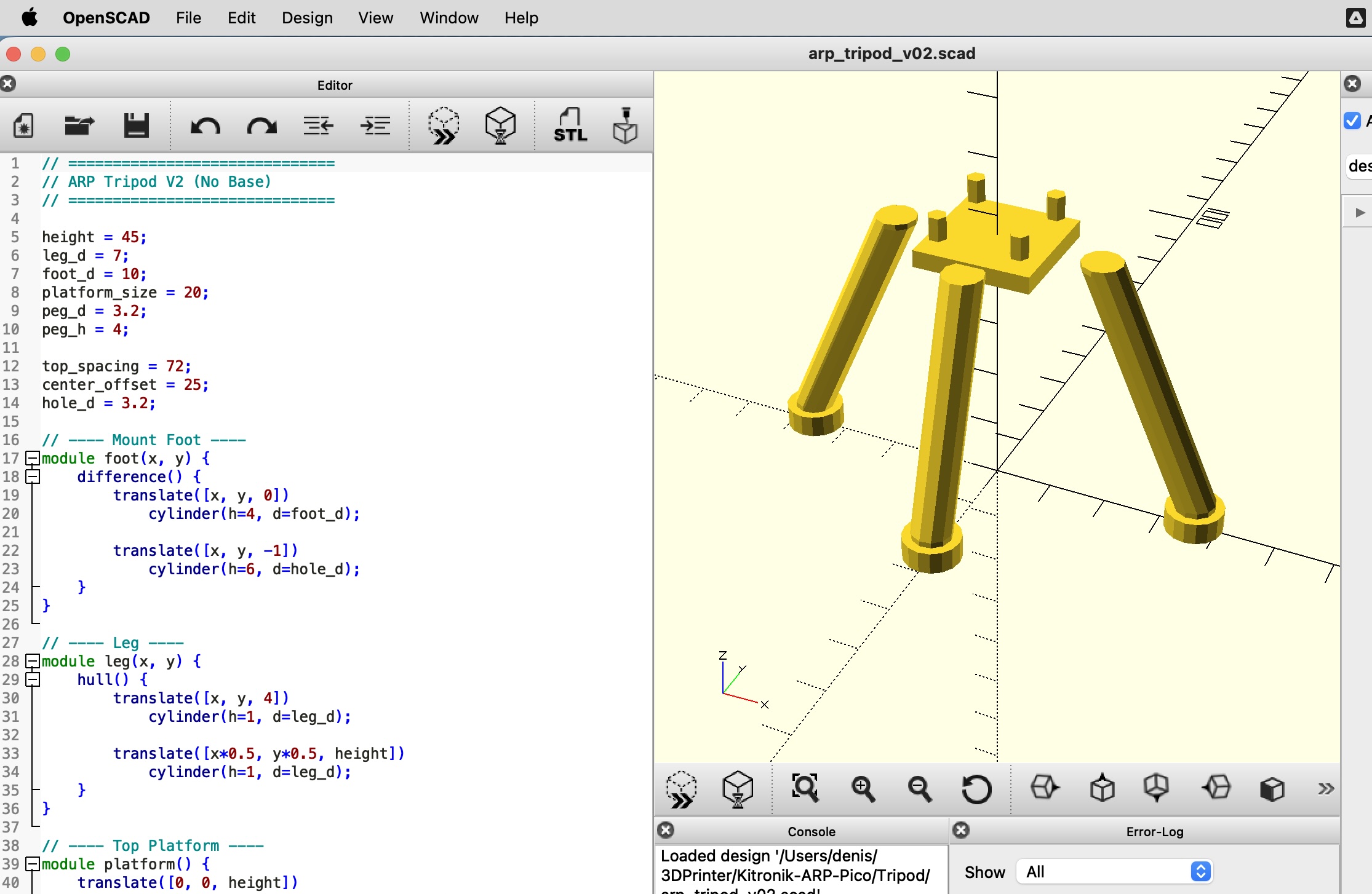
Oops, 2cm X 2cm platform won't cut it.
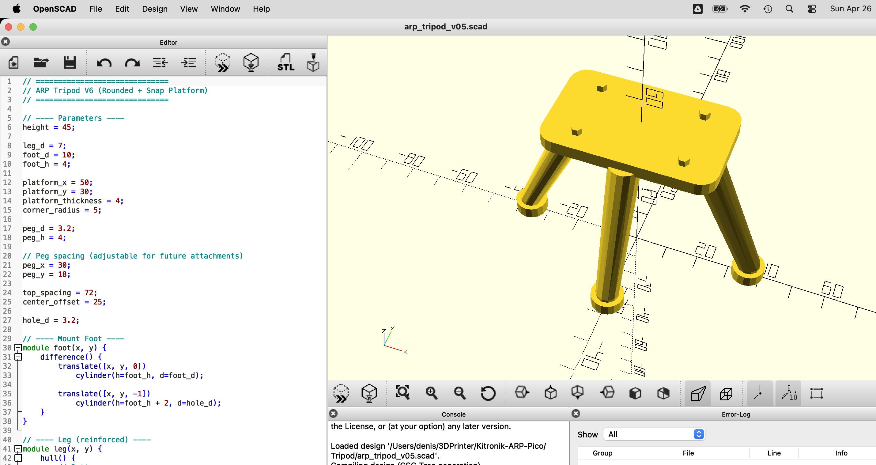
5cm X 3cm platform works. With rounded corners.